I must state for the record that at the beginning of this saga, I never intended to let things get this complicated. Along about 1989, I thought it might be nice to have a single rack in the shack to support an ART-13 and BC-348, similar to the rack in Flak Bait (the National Air & Space Museum's Martin B-26B), that has a BC-348 and an SCR-274N command set installed. The intent was simply to construct something that resembled original installations in WWII aircraft, using dimensions and aluminum materials that led to easy assembly. As things developed, I added a 45 degree corner to it simply "to use the space a little better". Then of course I needed "just one more" wide bay - to hold a few more acquisitions and provide visual symmetry.
By now you should see where all this is going...
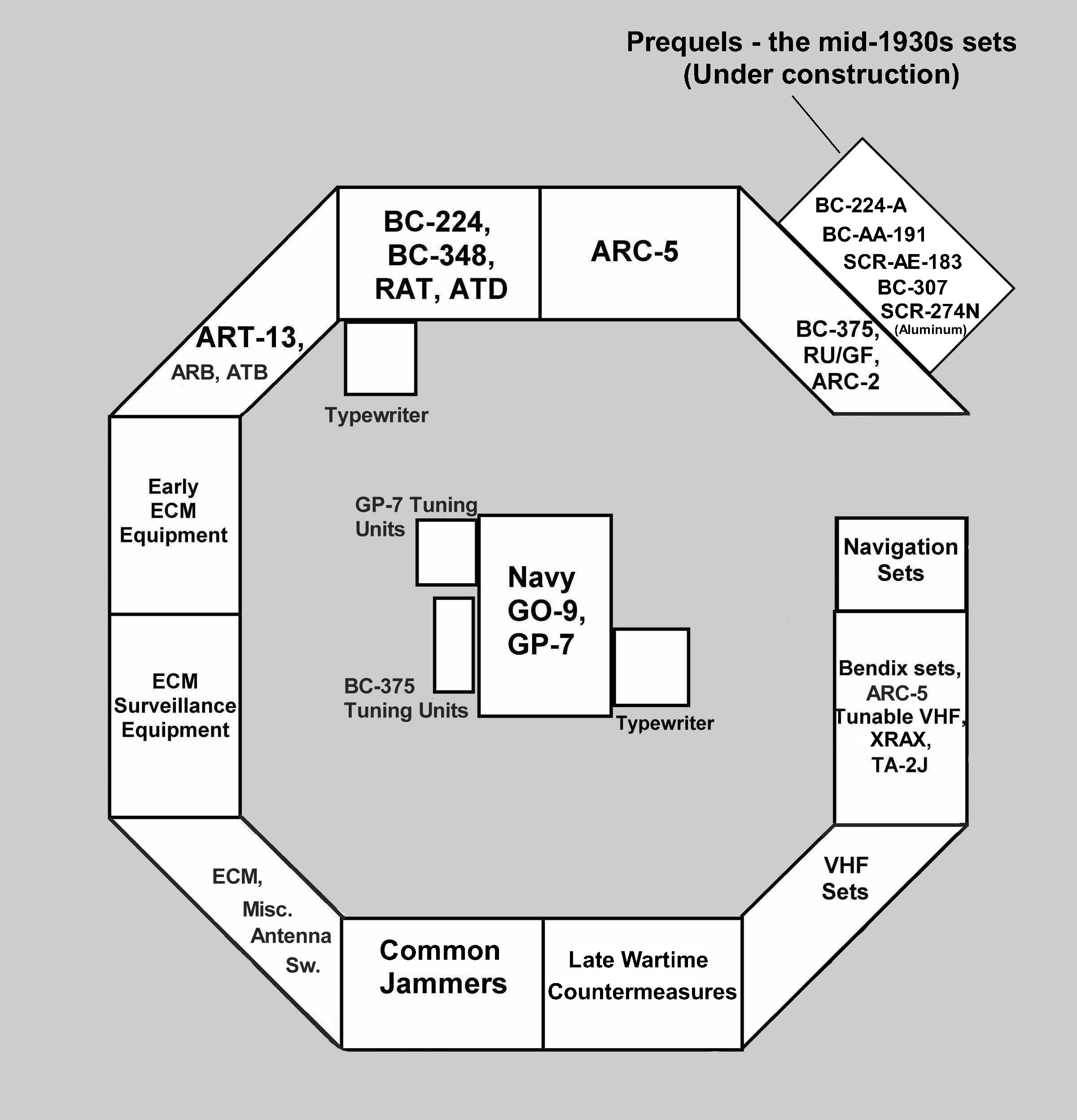
As you can see in the diagram, each of the bays is loosely dedicated to a particular theme, though the theme may be tenuous at times, or have discontinuities. The labels represent the primary radio set (or sets) that defines the position, but others are squeezed in as well. Starting at the upper right hand corner and proceeding counterclockwise, the links to each of the fourteen bays are as follows:
Finishing off the octagon (I sincerely hope) is the new bay mentioned above (under construction), a late addition
to provide a home for some otherwise storage-cabinet-confined sets of significant historical significance prior to WWII:
Just to provide some scale for the above layout drawing, each of the wide rectangular bays is three feet wide by two feet deep by about five feet tall. The three foot by two foot dimension allows economical use of plywood from the home stores, and approximated the actual dimensions of those in avionics suites (especially countermeasures) in period aircraft. The use of varnished 3/4" plywood (actually 23/32" thick these days) has an impressive number of precedents in aircraft, but I chose to additionally sheath the top of each piece in .032" aluminum sheet, primarily to assist in solving the grounding problem that accompanies the use of WWII aircraft radios in a radio amateur environment. Anyone contemplating replication should be aware that this material dents rather easily from carelessly dropped items, so consideration might also be given to brushed stainless sheet if available at a reasonable price - at least for the main shelf.
The corner bays have a two foot wide front chord, but of course fan out toward the rear so there is some room at the back corners for peripheral boxes that do not require controls. All the vertical members, as well as the edging around each piece of plywood, is 1" x 1" x 1/8" extruded aluminum angle. This is approximately the same size as that used in WWII aircraft, but of course the originals were not extruded, but instead were made on large sheet metal bending brakes.

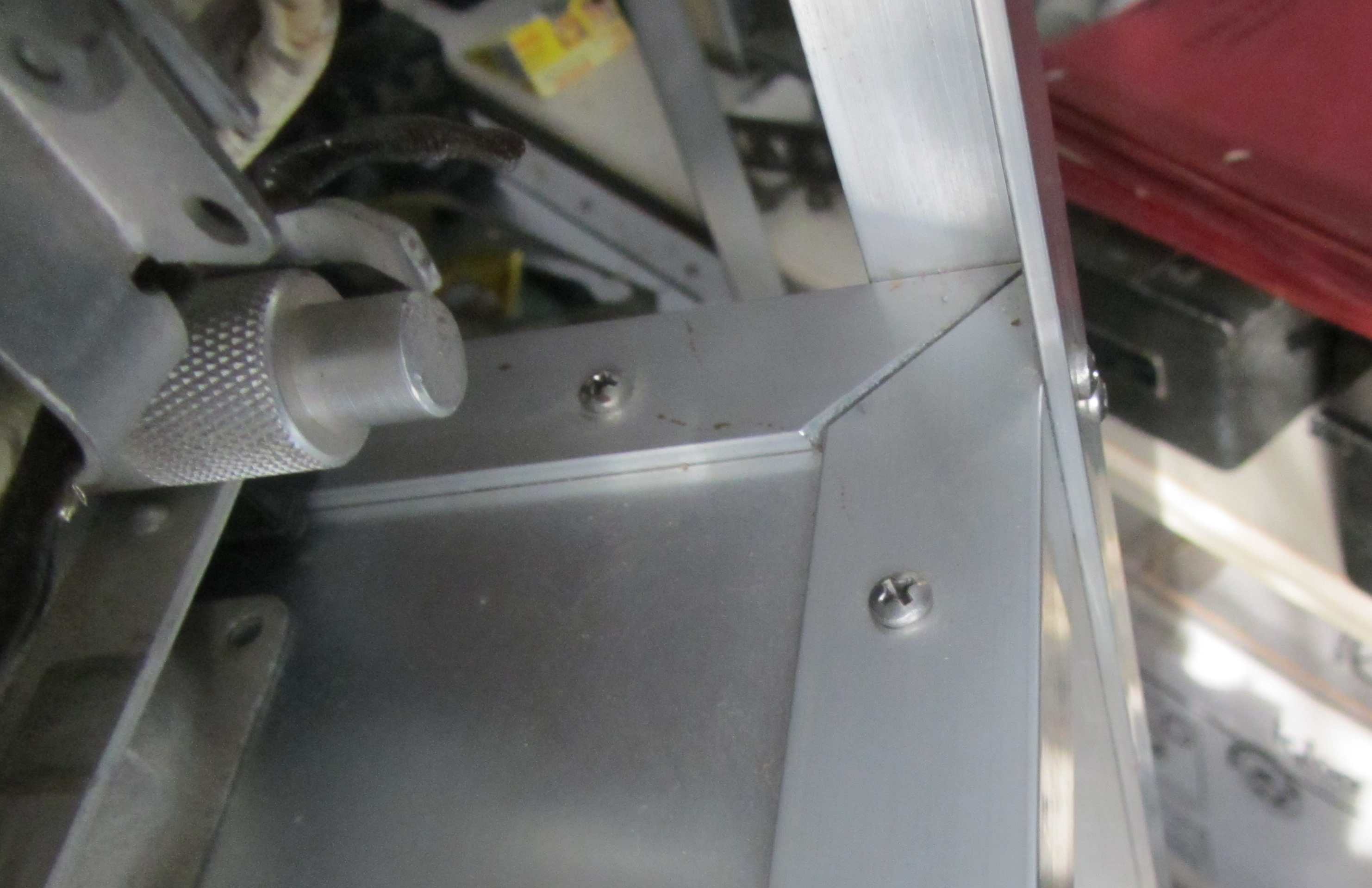
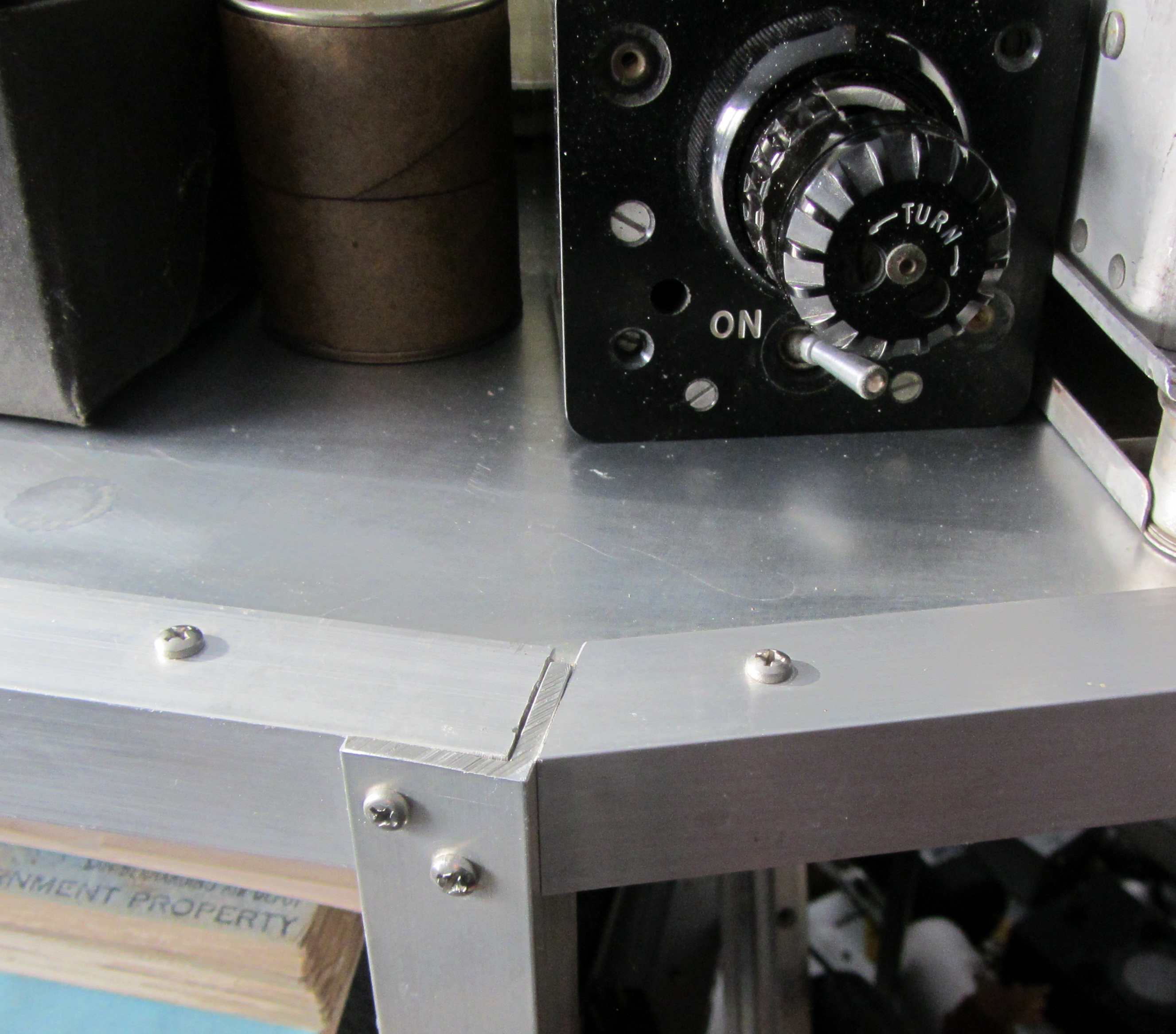
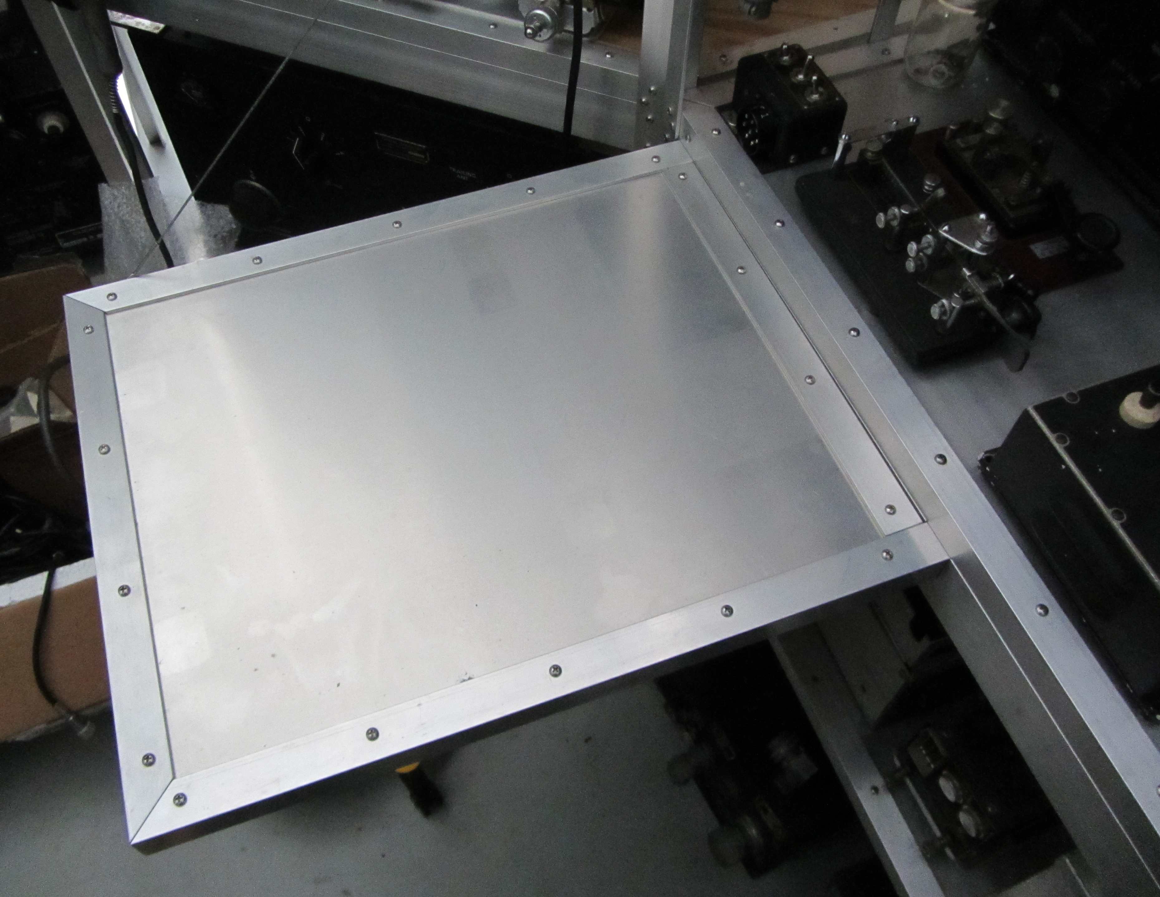
The plywood shelves are held onto these edge angles with 3/4" long #6 stainless sheet metal screws on 4" centers. I predrill the holes with a small pilot drill to minimize splitting of the plywood and increase holding power. You don't want to skimp on the spacing because the entire weight of the equipment on the shelf is suspended by the mass effect of these sheet metal screws, which are all in tension with equipment on the shelf. The edging on each shelf is mitered at each corner in a 45 degree angle as shown above. The shelves are then fastened to the vertical support members with #6-32 x 1/2" stainless machine screws, using tapped holes in the shelf edging. Four screws are used at each attachment point, staggered at a 45 degree angle so that they do not run into each other in the corner of the plywood. The fabrication sequence is to make all the shelves first. You then use picture frame clamps to attach the four legs to one shelf and drill/assemble that subassembly, then add the other shelves one at a time. I use a pair of variable speed electric drills to both drill and tap during this assembly operation, then disassemble the shelves from the vertical members and enlarge the tapped holes in the vertical legs for "through" clearance so that I get a good clamp upon reassembly. The only other power tool that is useful for this work is a small chop saw with an aluminum cutting blade. Wear ear protection! It's harder to describe than it is to actually do, and is a nice Saturday afternoon project once you have all the pieces cut to size.
One thing that this type of construction facilitates is the grounding aspect that drives so many folks to drink during operation of these sets. There are tuned ground effects that are particularly puzzling to operating the sets on the ham bands, partly because almost all WWII HF sets are simple MOPA designs, and as such are easily detuned by simply putting a hand on a part of the set. Grounding and bonding goes a long way toward eliminating these effects, and what better way to do it than to replicate the interior of an aircraft? My final step is to bond each rack to its neighbors once it is moved into its final place so that I have a solid ground plane all around the octagon. There are several ways to do that, including sheet metal clips, braided ground wire jumpers, or a solid bus bar arrangement. As long as you have solid connectivity with a large cross-sectional area, any method will work fine.
The flight deck is one of those endeavors that never has an end, it seems. Things are constantly changing, and future improvements include a new varnished plywood floor similar to that in the Enola Gay (see the Weird stuff page) and mounting of the aircraft chairs in front of the positions on adjustable seat rails.