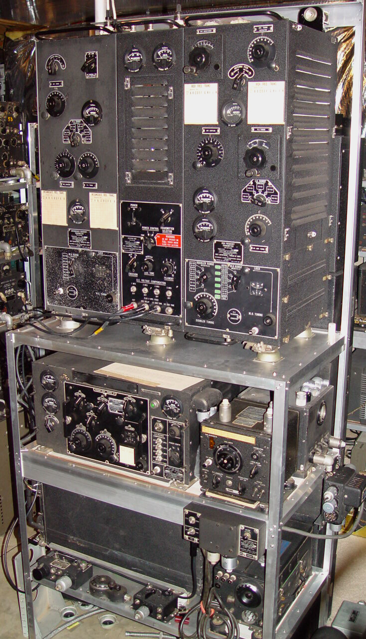
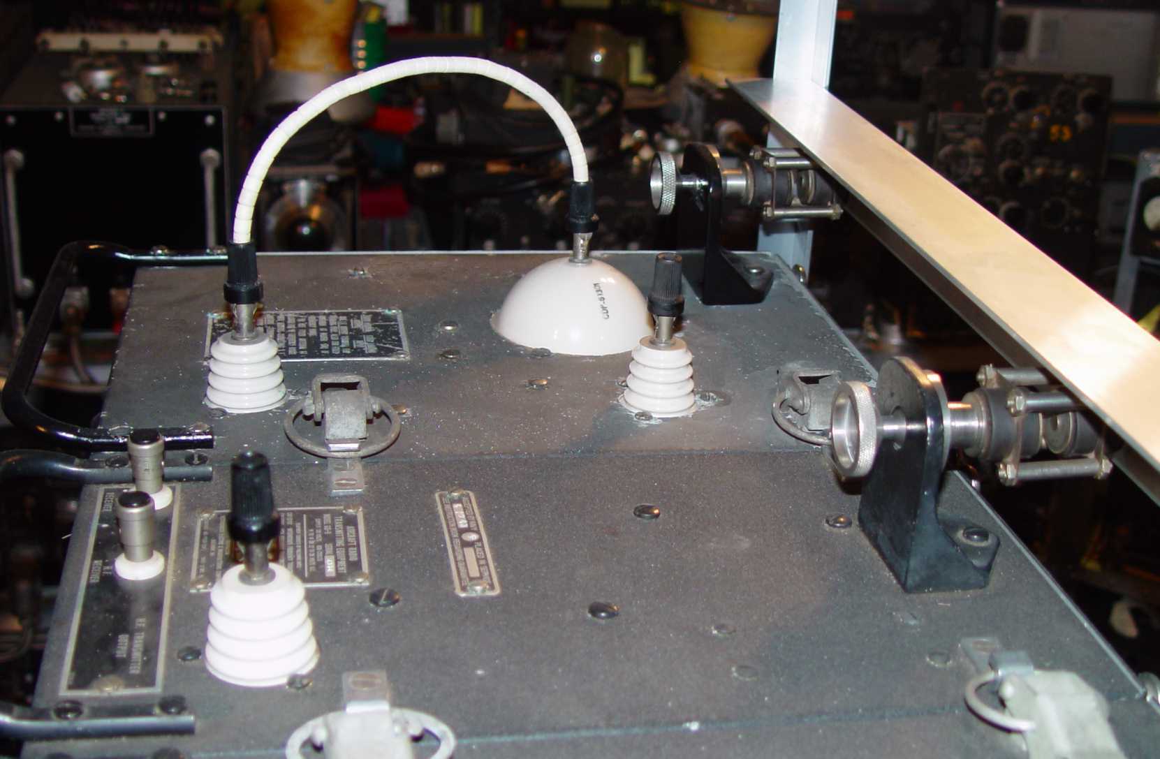
The 1930s represented a time of rapid communications systems development for the Navy, led primarily by efforts at the Naval Research Laboratory, but also by various manufacturers like Bendix and Westinghouse. Naval nomenclature for the sets of the time generally followed a variation of today's software release philosophy, with an original set having only the code letters of its type assignment like GO or GP, and subsequent improvements reflected with -1, -2, and so forth. The GO-9 100 watt HF/MF transmitter at the top of this photo is the last in the GO line, just as the GP-7 transmitter beneath it is the last of the GP line. This naming convention began being corrupted with the introduction of three letter designators. For example, the RAT receivers seen elsewhere on this website were also issued in a RAT-1 configuration, the -1 signifying a 28v power variant of the basic set. At the same time, the ARD countermeasures receiver mentioned in the Old Crow's Corner saw ARD, ARD-1, and ARD-2 designations successively issued with the same 28v power requirements, but with improvements at each step.
The GO-9 is by far the physically largest HF and MF transmitter set designed for aircraft, and competes for the heaviest based on documented weights - this despite both it and the GP-7 below it requiring 800Hz power in an attempt to reduce avionics weight. It is all the more surprising when you consider it lacks a modulator of any sort - only the TBW version intended for ground use had an AM capability. No remote control was available - without the ability to switch channels in a discrete jump, a radio operator was necessary anyway. These sets were primarily used on long range Navy patrol aircraft, and were still being carried around in those planes as late as the 1950s.
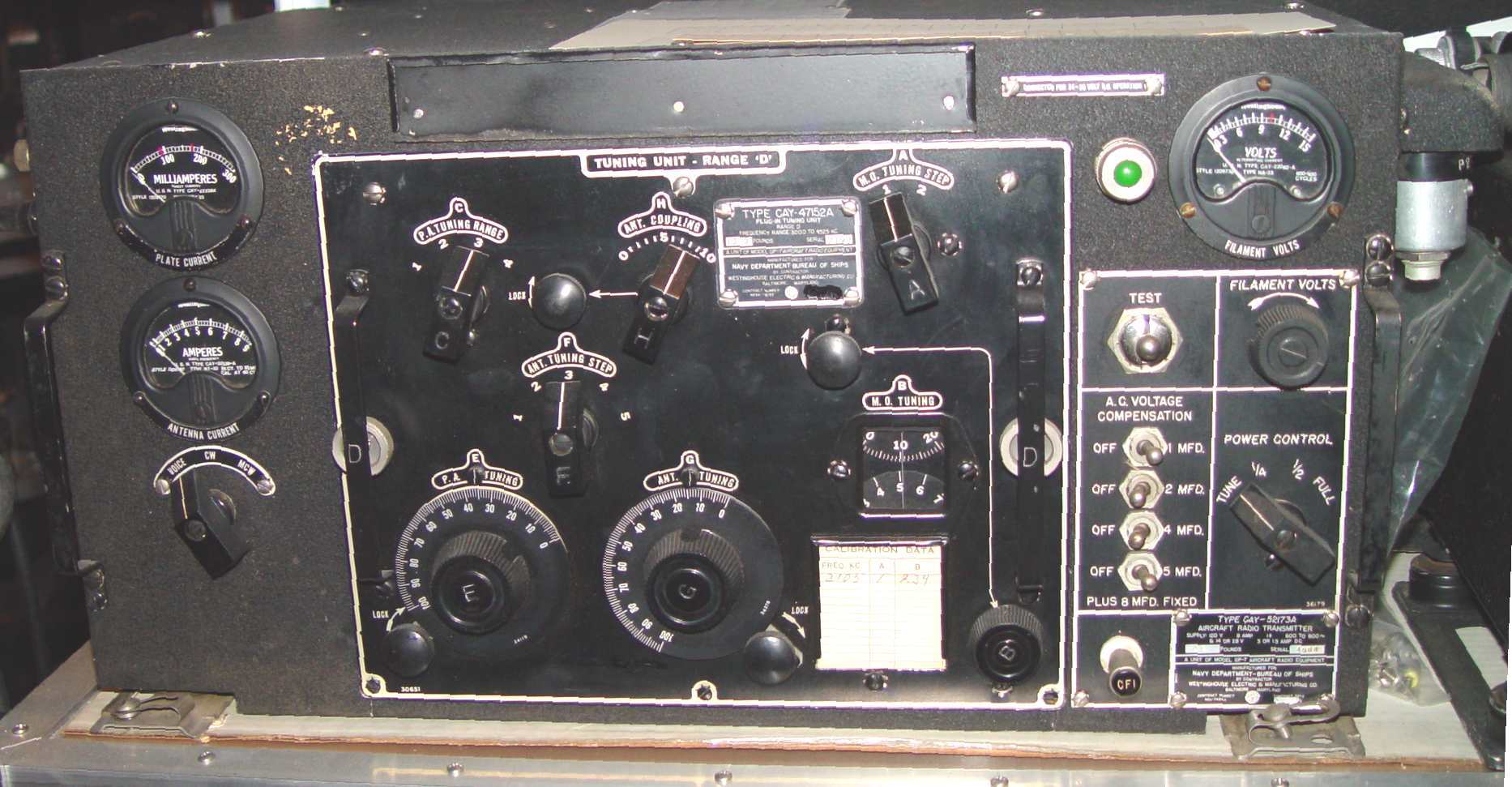
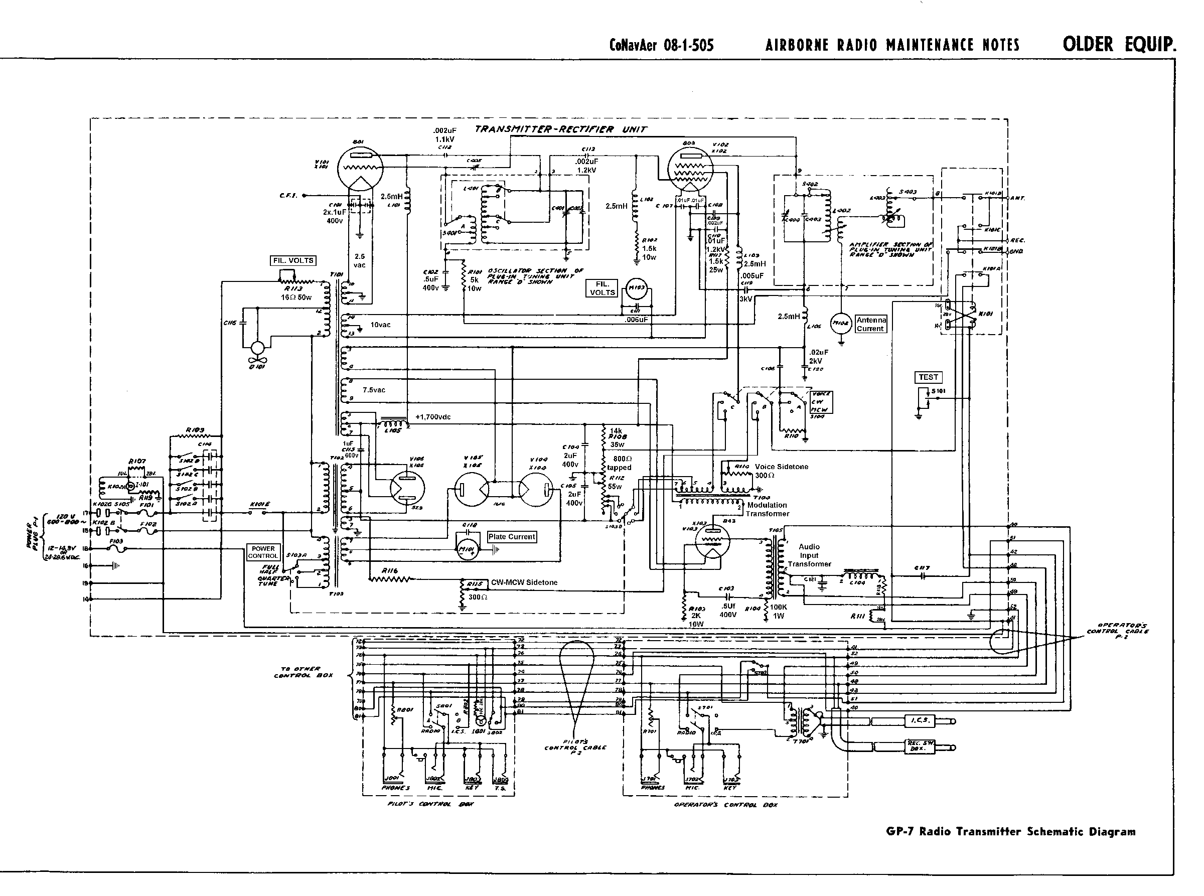
The GP-7 transmitter below it was somewhat of an improvement over the GO. It was certainly lighter, though with six plug-in tuning units it takes up about the same volume. It also had the capability for an AM mode, through grid modulation of its 803 final amplifier. Frequency coverage was 350kHz to 9,050kHz with the tuning units. A distant third in the competition to the Collins ATC (ART-13) after the ATD, the GP-7 shared the 800~ power requirement beloved of the Navy during the last half of the 1930s and early 1940s, including the rather complex set of switches to equalize power factor with other varying loads in the aircraft at that high supply frequency. The need to set PA filament voltage was a fairly standard feature in the higher powered 1930s sets - the GO-9 and Signal Corps BC-191/375 share it. (The ATC and ATD do not, but then they were fresh designs in 1940, not retreads.) A schematic of the GO-9 with parts values is located here.
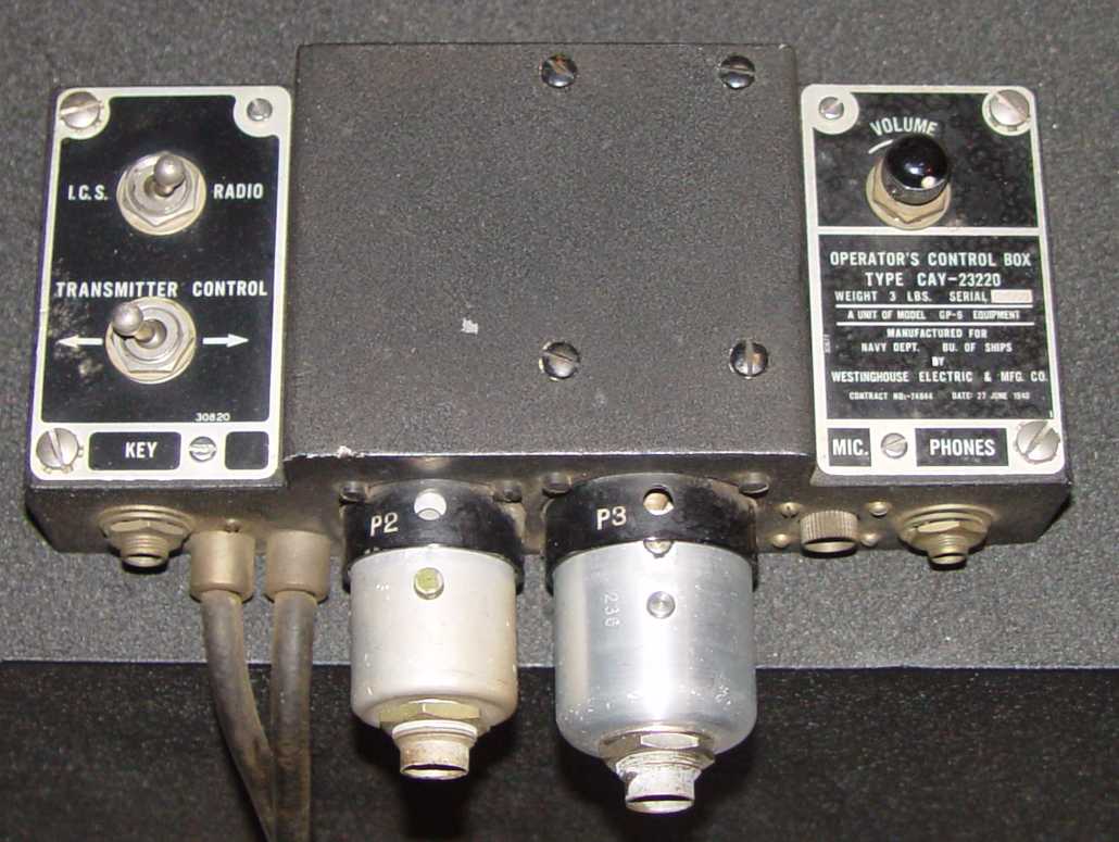
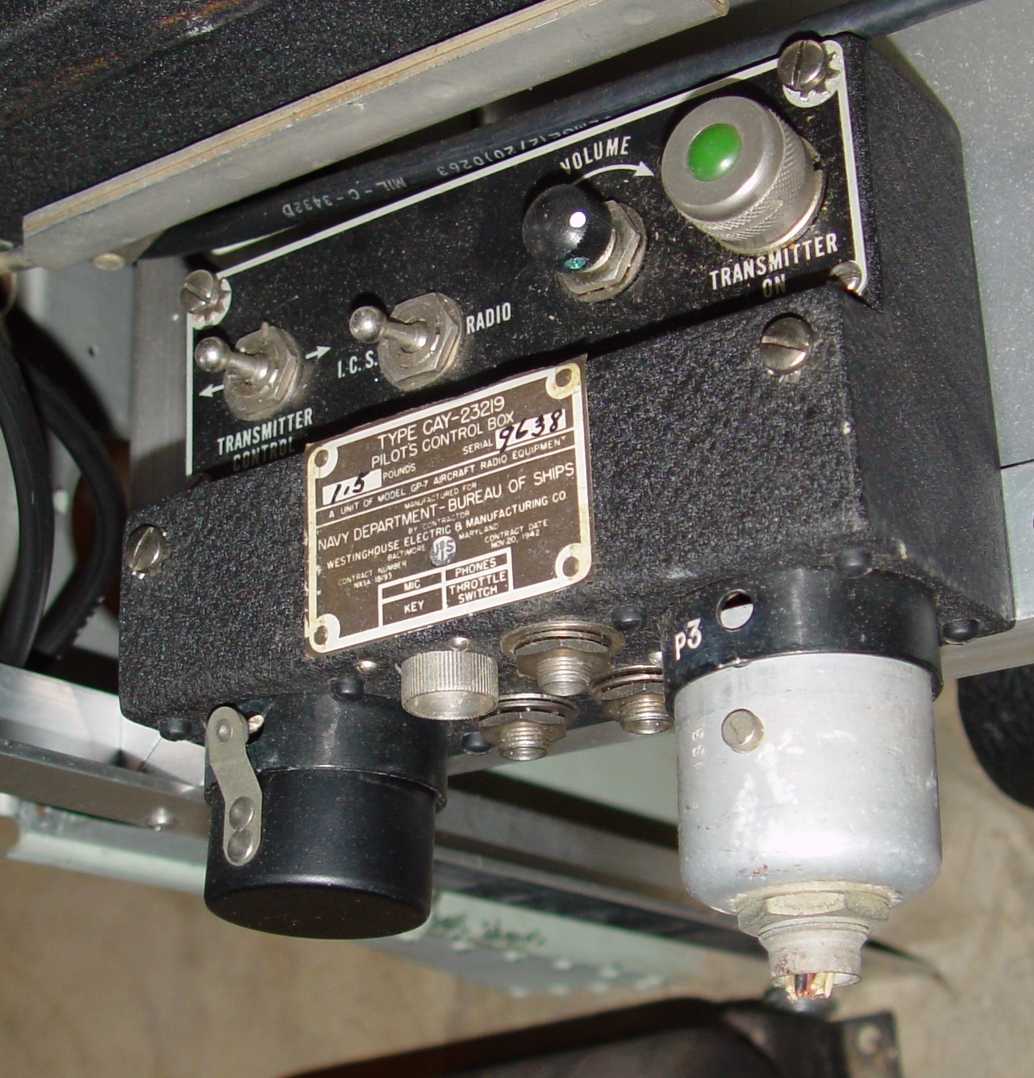
The LM-** frequency meter to the right of the GP-7 was essential for accurate frequency setting of transmitters of the period, and there are "CFI" terminals on all of them to permit connection of this signal generator (CFI = Crystal Frequency Indicator...a Navy-unique term for their LM, the Army preferring the term "frequency meter" for their BC-221 equivalent). The LM power supply is to the rear. Directly beneath the LM is the radio operator's control box for the GP-7. Unseen is a pilot's control box for the GP-7, a smaller control with fewer functions.
