The B-17: Backbone of the AAF
One of the difficulties in assembling a vintage military aircraft collection that is actually
operational is the task of pairing associated equipment in a reasonable way. At times
it is simply impractical to do so, and that difficulty is reflected in this particular
corner bay of the flight deck Octagon.
It is composed of both USAAC/USAAF and Navy sets which have no contextual relationship
per se, other than this bay has randomly caught some stray dogs and cats that were relatively common
communications equipment in various theaters and aircraft.
|
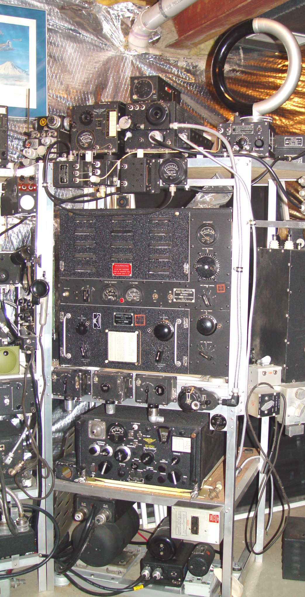
Jumping below the RU/GF set at the very top of this rack for a moment, perhaps one of the best known transmitters of WWII is
the BC-375, used in the thousands of B-17s and other medium and heavy Army bombers produced during the war. The -E version of that transmitter takes up a
good part of the vertical height in this position. Designed in about 1932 as a commercial set called the
RT-76-A, GE subsequently adapted it to military specifications circa 1935
in the form of the BC-AA-191. The BC-375 was a 28vdc evolution of that
first set, and continued to use the ancient (by 1941) Type 211 triode as push-pull modulator, M.O. (Master Oscillator), and Power Amplifier.
Interestingly enough, the BC-375 was also initially selected for the B-29, and early B-29 manuals
show mockups of the radio compartment with that set in it - that's one of the reasons
for the placement of the shock mount to the left of the radio operator in an
uncomfortably low position for the much more compact ART-13 that replaced it.
There was a total of seven plug-in tuning units available for this set, an approach that prevented
any channelized switching that the Navy demanded from their wartime developed sets. The use of
the 211 triode (VT-4 in Signal Corps parlance) with its large plate structure made
neutralization essential, and the simple MOPA design made keying relay sequencing
a matter requiring some skill. In fact, there was a TOOL
designed with lights that indicated closure of each contact as the antenna/keying relay armature was slowly rotated, so that contacts
could be adjusted for energizing in just the right sequence to avoid "yooping" of the
CW signal. It also required a "stiff" power supply with a low internal impedance,
a job the dynamotor at lower left performed admirably. Postwar conversions of this set
by radio amateurs earned it a bad reputation because these peculiarities were forgotten
or ignored. To the transmitter's right is a BC-306 antenna tuner, used with the lower frequency
tuning units.
The large dynamotor on the left at the bottom of the rack is a PE-73-*, which produces 1,000 volts
DC for the BC-375. The smaller dynamotor in the center powers the RU and GF set on the top shelf, while
the even smaller one on the right is the PE-86-* for the BC-347-* interphone amplifier
just above it. The BC-347 was the heavy aircraft intercom for the AAC/AAF
for most of the war. It was not until 1945 that a combined amplifier/dynamotor
began to be installed in AAF aircraft - the AM-26/AIC-2 - an amp that looked
very much like a command receiver. For more on these interphone sets, see the
Interphone page.
|
Below the BC-375 transmitter is a Collins AN/ARC-2, also shown below. This particular one is a rare original
contract issue set. Integrating transmitters and receivers
into a single transceiver became a popular way of reducing the "box count" early in the war,
and the trend that was begun in the VHF sets began to be seen in the HF realm as well.
It was actually pioneered by Bendix in their RTA-1B, though this Collins set shared
little with that design other than the same general size. It followed Navy requirements
in having channelized autotune capability, though with only eight channels rather
than the ten that the ATC and ART-13 enjoyed.
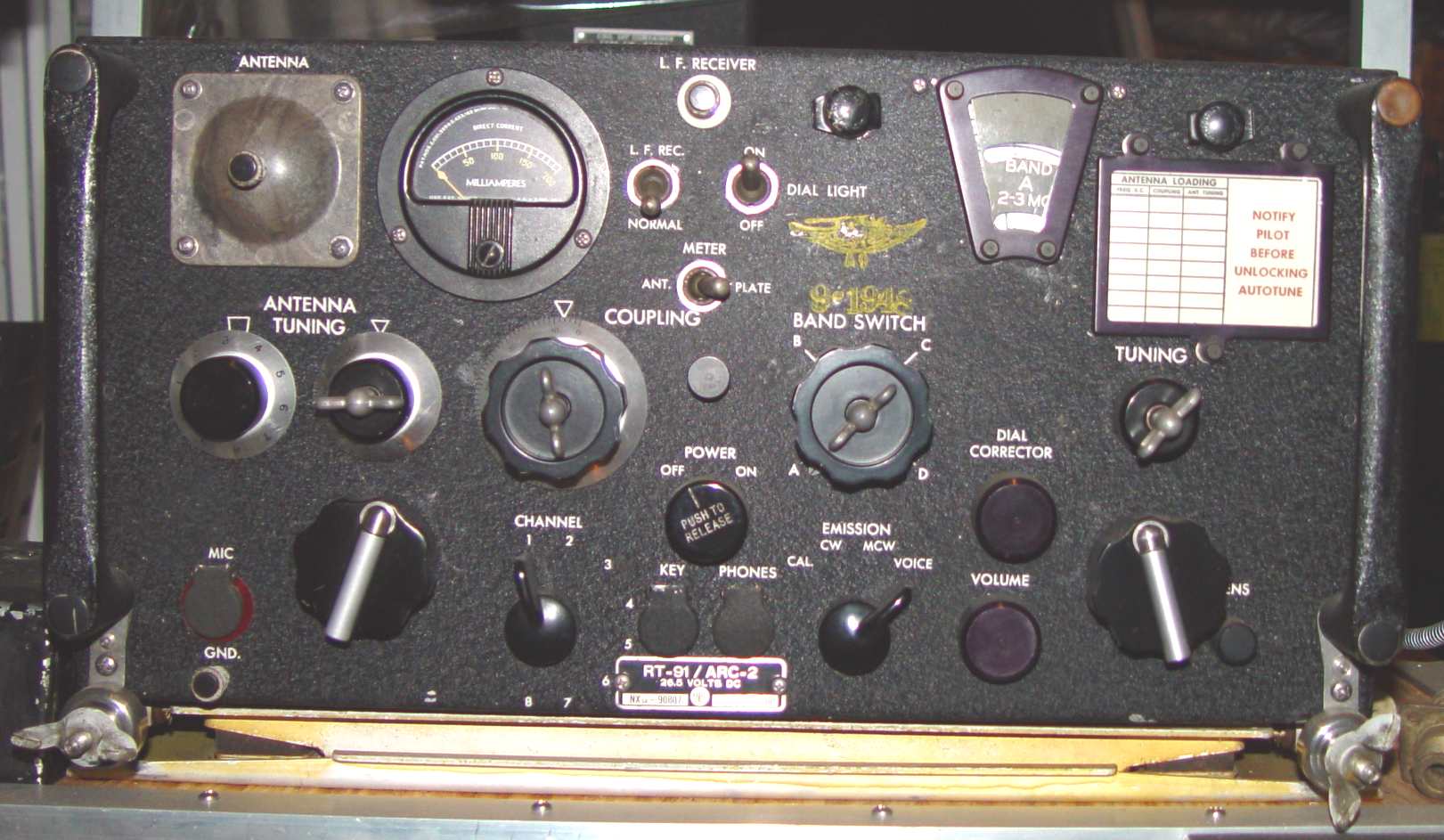
AN/ARC-2
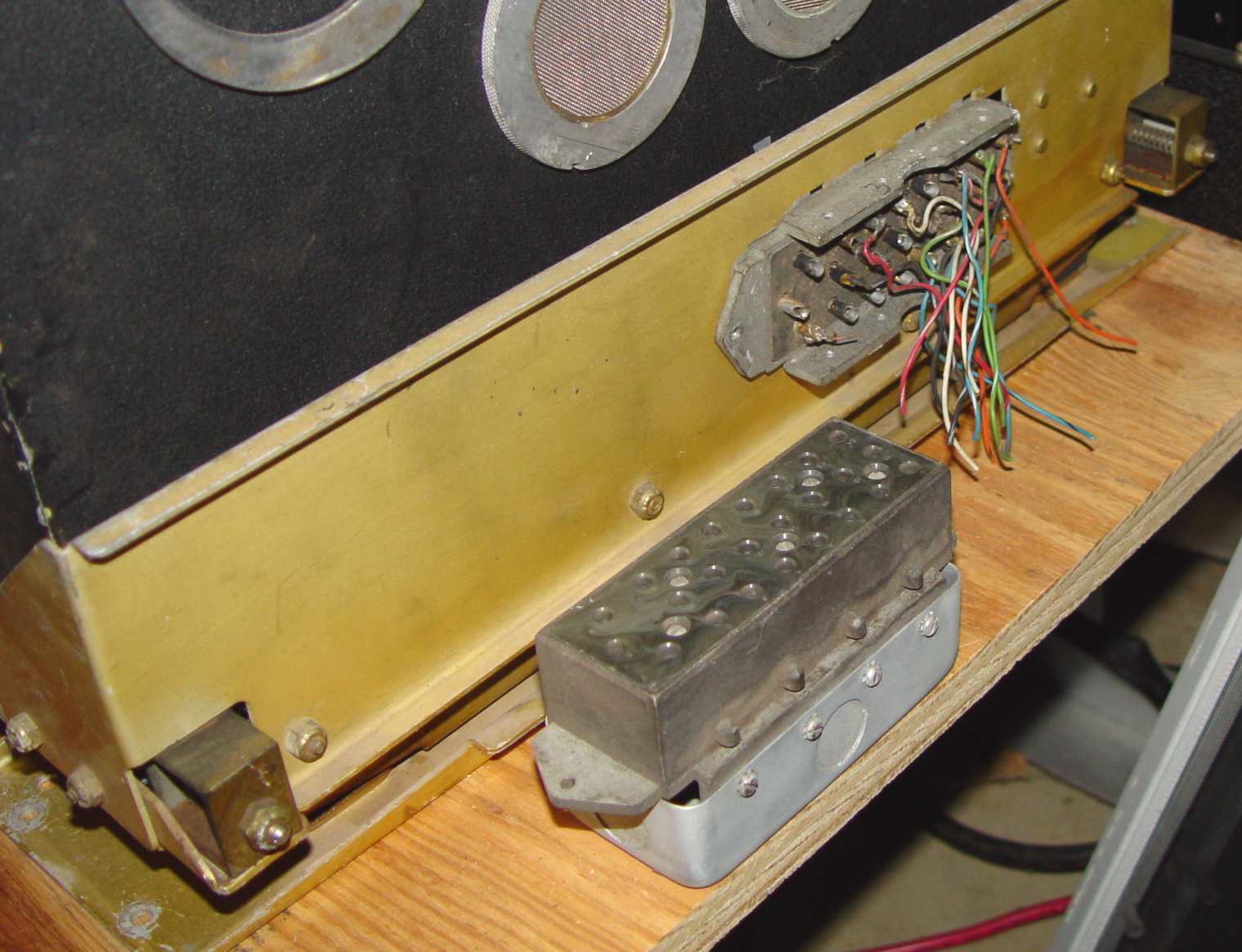
Unique rear connector for AN/ARC-2. As far as I have been able to determine, this set
and the AN/ARR-15 receiver were the only two pieces of equipment that used this unusual connector.
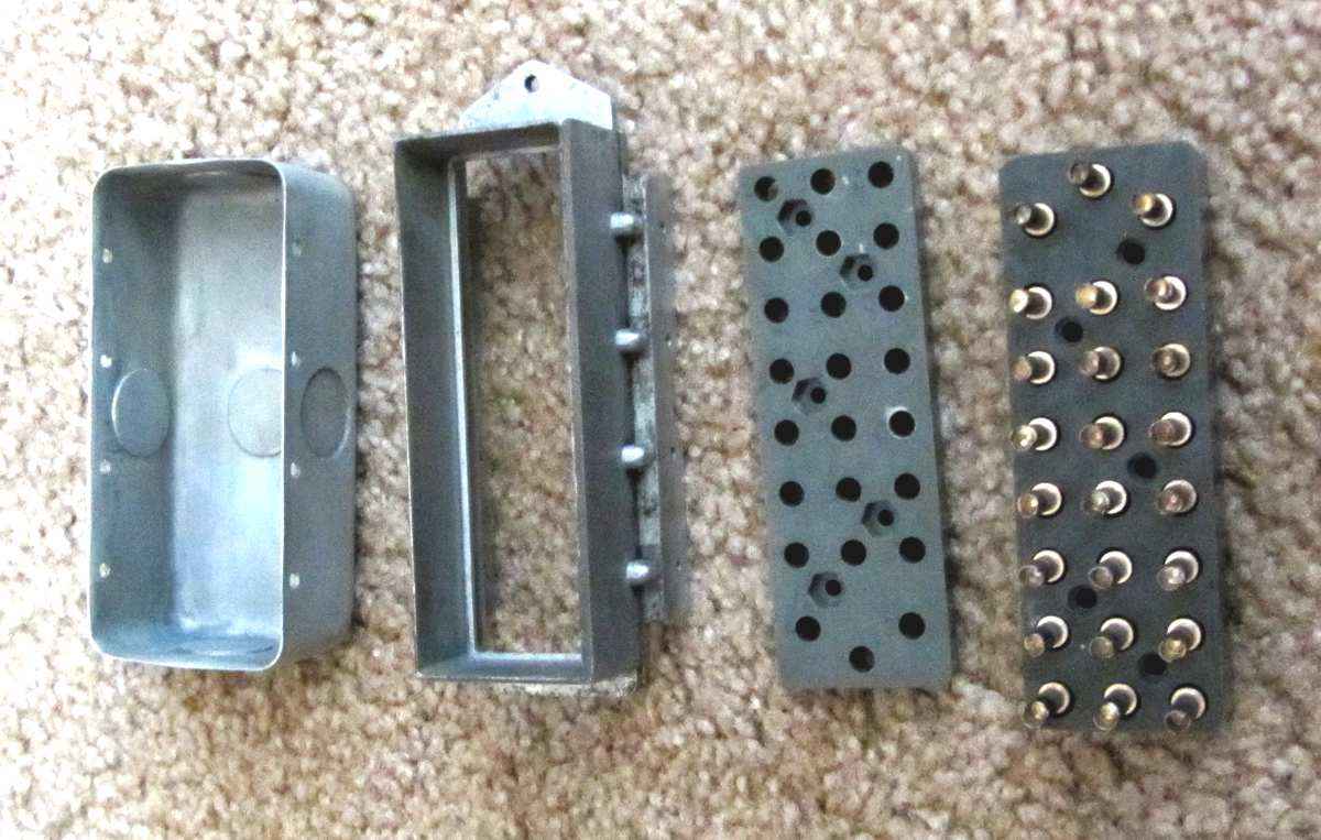
ARC-2/ARR-15 rear connector piece parts.
Returning to the top of the bay is the Navy RU/GF set, also shown below. This is another set that was originally
designed in the early 1930s but had an amazingly long service life. This particular
set is composed of an RU-15 and a GF-5, though the series finished up with RU-19
and GF-12 models (these two particular components were not paired as a set, however.) Somewhere I have a document
that talks about an RU-20 receiver, but until it resurfaces we'll just end the series with the RU-19 for now.
There were minor variations in frequency ranges, with the earlier ones tending toward the lower frequencies - the GF-5 actually has a 1200-1500kHz coil set.
An optional part of the set was the DU loop antenna at right. More on the DU-* is located
here.

RU/GF system
Presaging the complexity of the later command sets, there are numerous pieces to this set.
Five of the RU/GF control boxes are lined up below the BC-375, counting the "coffee
grinder" tuning control and remote coil band switch just beneath it. The antenna relay,
an unun impedance matching device, a dummy load, and tuning/alignment meter are directly under the set above the BC-375,
with the nose of the set junction box seen at the same level on the far right.
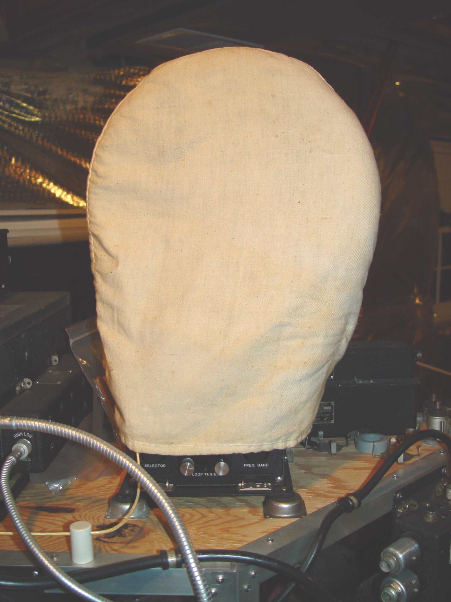 DU canvas cover
Most of the Navy sets had canvas covers to help ward off condensation and rain water, both
of which were endemic in profusion in Navy aircraft of the period. The cover for the DU
shown here differed from the usual cover in not having the "starch" that kept it stiff and
erect like the other covers, and not covering down cleanly to the bottom of the set.
Return to AAFRadio home page