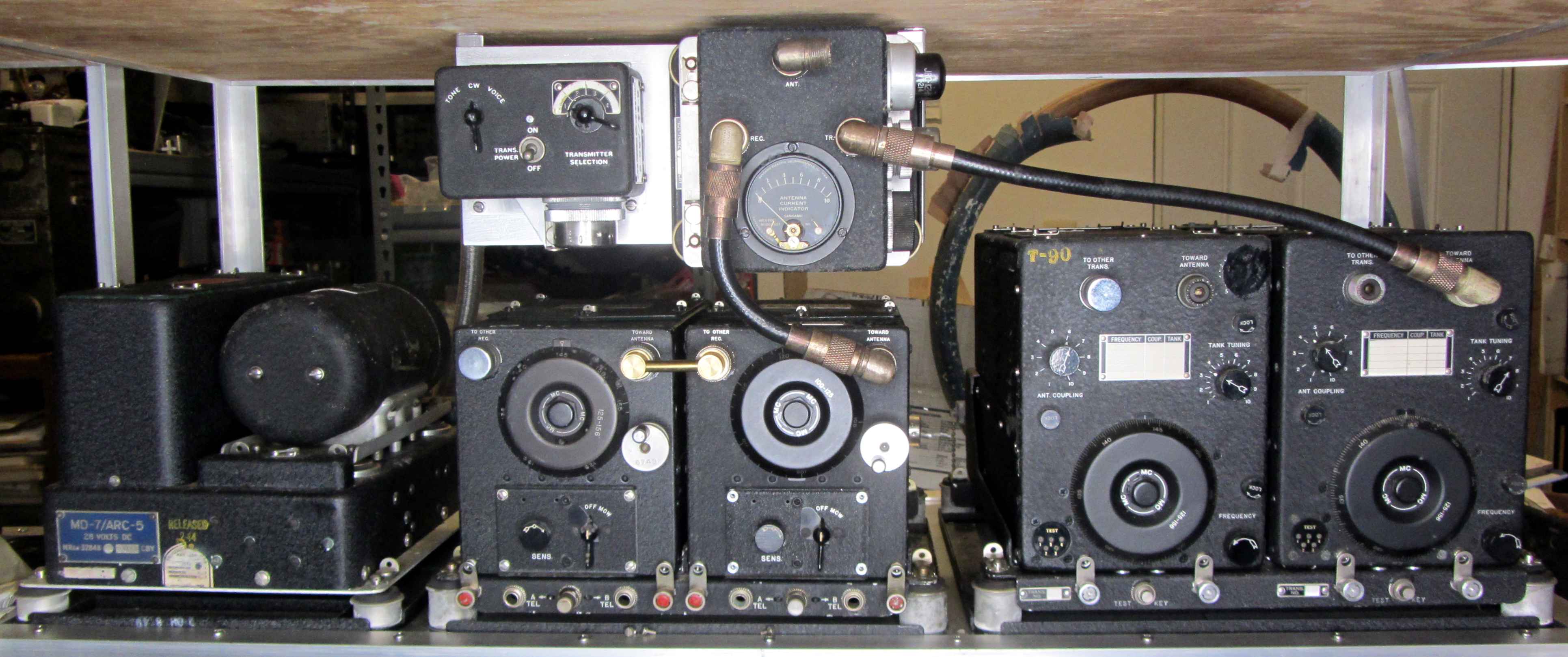
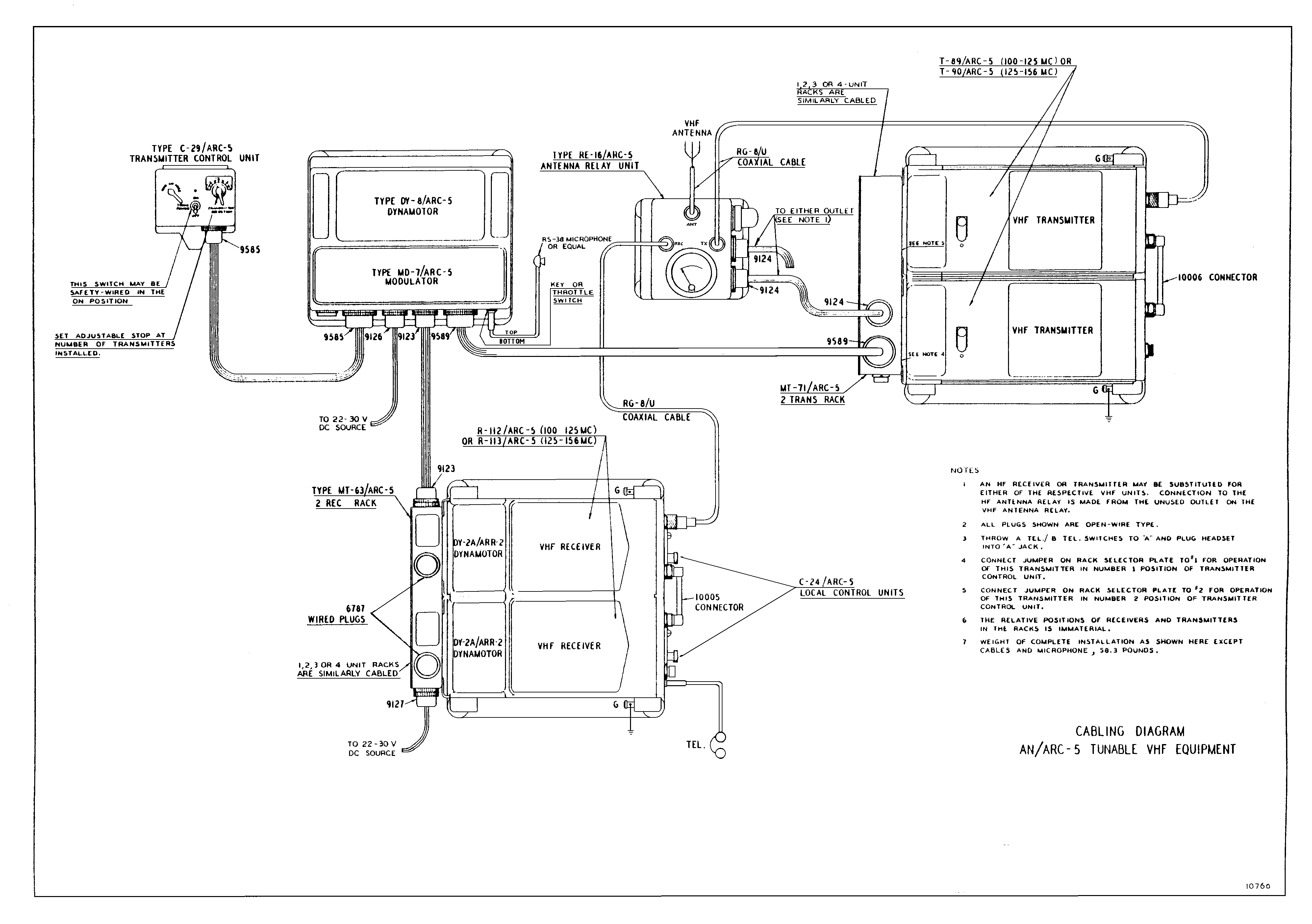
In the summer of 1944, ARC produced a small number of tunable VHF sets for Navy evaluation. The primary driver for their development was the early difficulty in providing enough cystals to enable stable channelization of the aircraft sets. Unfortunately, the development came at a time when crystal manufacturers were finally getting production and quality ramped up to the quantities needed. Faced with that nexus of supply versus need, Navy procurement officials declined to pursue a follow-on contract, though as noted below the receivers became the foundation for postwar ARC commercial VHF sets produced in the thousands. Shown here is the entire 1944 installation diagrammed in the brief 21 page supplement to the ARC-5 manual (missing only the T-89 100-125MHz transmitter, which of course I would love to find someday...another T-90 is standing in for it at the moment). From left to right, MD-7 modulator, R-113 (125-156MHz) and R-112 (100-125MHz) receivers (C-29 transmitter control and RE-16 antenna relay suspended above), and T-90 transmitter (125-156MHz.) The cabling diagram for this set is shown below:
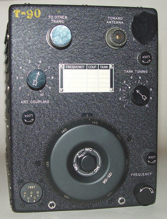
Performance curves for this set are shown at Tunable VHF ARC-5 set performance curves . Following ARC's penchant for reusing components that met their stringent requirements from other sets, both the RE-16, T-89, and T-90 used the same antenna relay contained in the more common T-23/ARC-5 and T-67/ARC-3 VHF transmitters. The RE-16 also contained a 12H6 rectifier used to rectify the carrier for an antenna voltage indication (as opposed to the the usual antenna current meter), and two control connectors so that a normal HF set antenna relay could be daisy-chained through it. That allowed a single C-29 control box to control both HF and VHF sets. The test point access at lower left on the transmitters reflects the evaluation status of these sets, and according to the manual was planned to be removed in a larger production run.
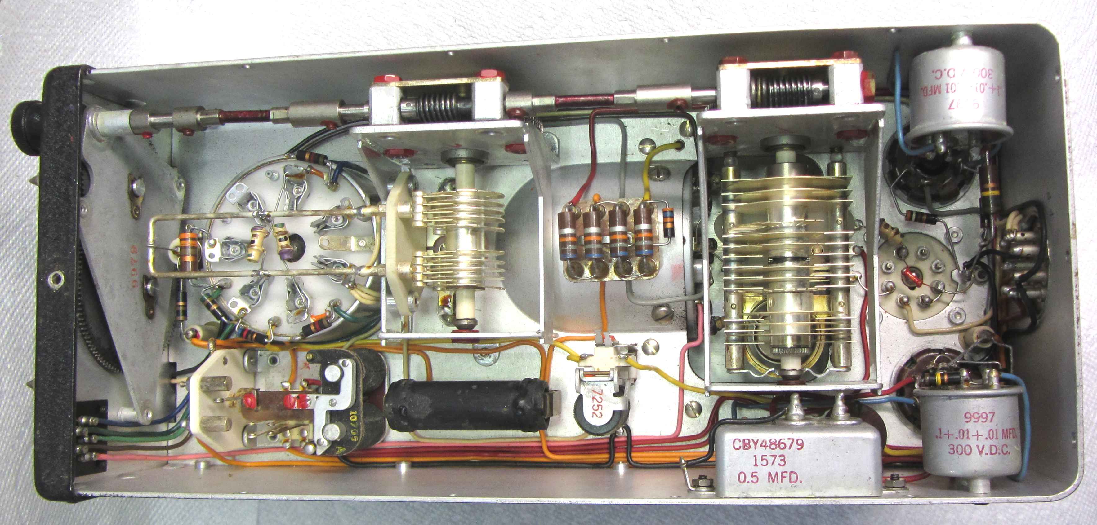
The receivers eventually morphed into the postwar ARC Type 12 and later VHF sets with very little change other than paint color, loctal tubes, front panel frequency dial deletion, and substitution of copper wire in the brass wired 15MHz IF transformers that was originally intended to broaden the response curve for aircraft comms in 1944. The front end preselector, using four miniature vacuum tubes, is a marvel of careful parts placement and design. The local controls, unique to these two receivers, had black lacquered sheet metal blocks placed on the mode switch to prevent selection of CW, which did not exist in this set designed soley for the command function (plane to plane and plane to control tower). The "MCW" term also covered AM voice mode, and was a holdover from the original 1939 RAT and ARA receiver local control boxes which had the same labels.
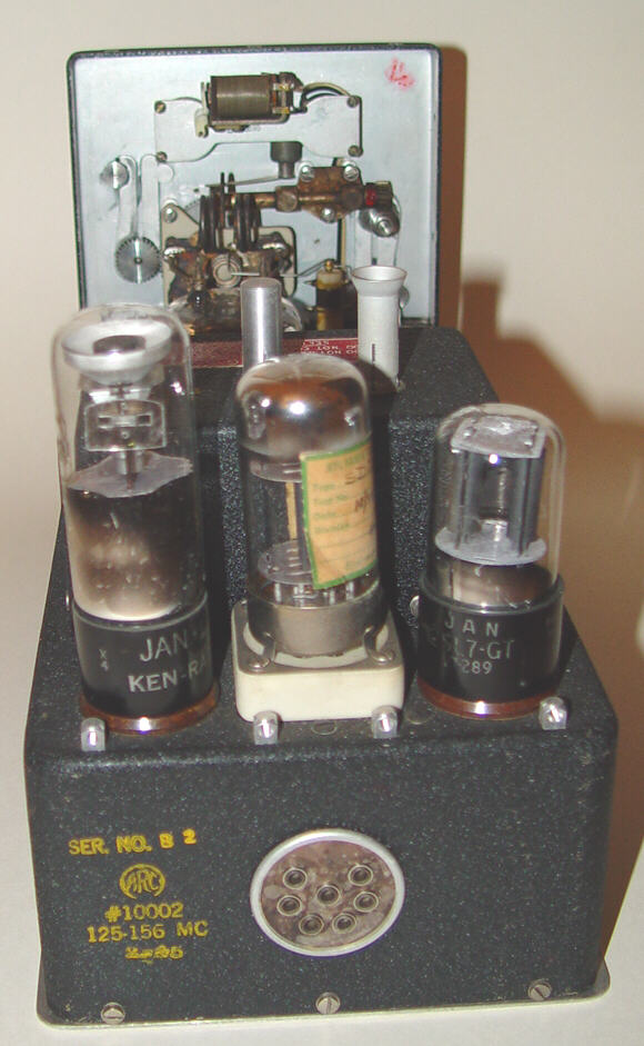
Production figures are said to be in the region of 100 or so. The majority of these sets received official Navy nomenclature tags and were actually issued for Fleet evaluation. Others, like the T-90 on the left from the ARC Morgue, had only the model number stamped on the outside. The 125-156MHz receiver on the left in the photo above is serial number 3!
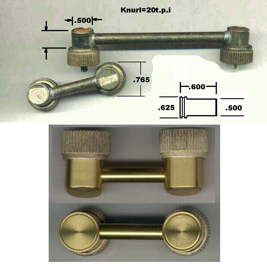
This equipment used a coax link between sets in each rack that was unique to them. It was a sort of home-brew hardline to minimize losses. A photo of these original hardlines is below, along with one I fabricated below the originals before silver plating is applied. You can see some details about the replication of these hardlines over on the Garaj Mahal web page (under "Coax connectors").
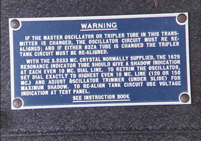
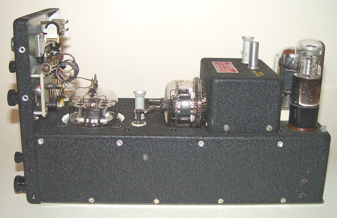
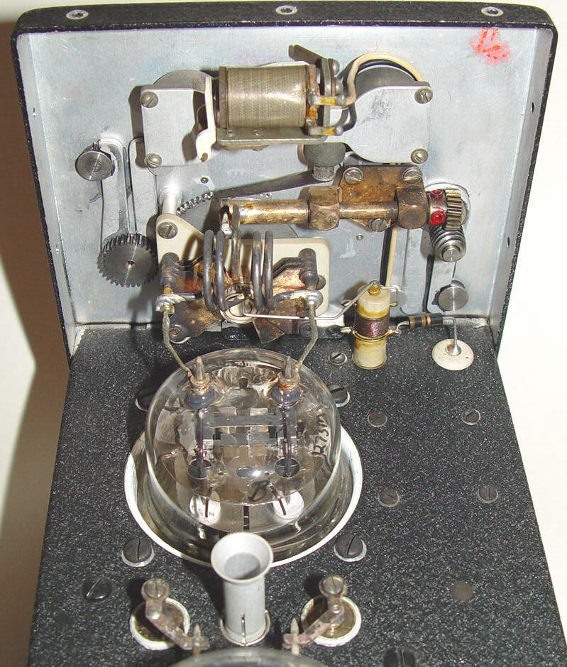
The transmitters were of fairly conventional design, using a MOPA approach with an intermediate 832 frequency tripler for the design. As with all the ARC low volume equipment, these are finished like Swiss lathes and great care was taken to ensure mechanical rigidity. This was especially important since there is no crystal to establish initial stability - the crystal in the enclosure is for calibration only, identical in concept to the lower frequency command transmitters. A Sylvania "SD-838" prototype tube was used as the Master Oscillator - a 28v filament loctal triode that was necessitated by the lack of complimentary tubes to use within the transmitter for a series filament string. Data on the tube is recorded on a piece of paper pasted onto the glass envelope! More photos of this transmitter are below.
