Switch Bay
 Every shack has its stray dogs and cats corner, and this one is no exception. The intent of this bay is a
bit ragged at the moment. The overall hope is that someday it will serve as the antenna patching locality,
where different antennas can be matched up with any receiver or transmitter on the flight deck.
Every shack has its stray dogs and cats corner, and this one is no exception. The intent of this bay is a
bit ragged at the moment. The overall hope is that someday it will serve as the antenna patching locality,
where different antennas can be matched up with any receiver or transmitter on the flight deck.
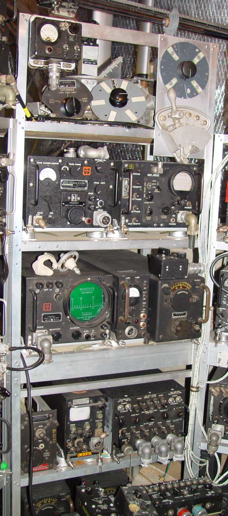
Right now the lower levels are temporary storage locations for some equipment that doesn't fit anywhere else.
On the top shelf are several types of coaxial antenna switches that were specifically designed for the low
losses and careful impedance matching required to get every last shred of signal out to (or from) the aircraft antenna.
The Navy was the most prolific with these antennas on their patrol aircraft, and therefore favored the
12 position SA-14/APR-1 switch with the large circular faceplate mounted at far right. The USAAF, even in the B-29 RCM
installations, had fewer antenna options and used a maximum six position switch
(the SA-44 at center), this one destined for a APR-2
receiver. A three position variation of the SA-44 (SA-69/APR-10) is also shown at the far left side.
The large quadrant to the far right is an interesting exercise in designing to the KISS principle, utilizing a series
of six type N connectors selected by a spring loaded male connector. This was specifically designed for the AN/APR-4
surveillance receiver.
On the second shelf on the left is an AN/ARQ-1, a
transceiving jammer targeted at ground communications that was self
contained, with manual scanning capability and the ability to switch to jamming when an enemy signal was detected. Its
frequency range was roughly 14MHz to 50MHz. To the right is a placeholder - an
AN/ARR-8B motorized scanning receiver
that will someday be replaced by an original 5" scope AN/ARR-8A
model if I can ever find one. It has a frequency coverage of 70 to 300MHz in two bands, taking up where the ARQ-5 below
leaves off.
On the third shelf down, the scope on the left is another motorized scanning receiver with panoramic display, the
AN/ARQ-5. Covering 20MHz to 80MHz
in two bands, it was another attempt at increasing the "probability of intercept" by more rapidly scanning the range of
interest. Most of the 5" scope designs were abandoned in later equipment because the larger diameter added no real advantage to what was
pretty vague frequency and signal strength indications. Having found a signal of interest, the operator would normally
shift to an APR-4 for analysis (or in the case of the Navy, the immediate predecessor of the AN/APR-4 countermeasures receiver, the
AN/APR-1 to the right of the ARQ-5.)
At the very bottom is a jumble of boxes, a portion of which form part of the
AN/AIC-5 interphone system. Since they
gravitated here by osmosis, and in fact represent the interphone set with the greatest flexibility of all those in the
flight deck, I'm giving some thought to simply permanently installing them in this bay.
Return to AAFRadio home page