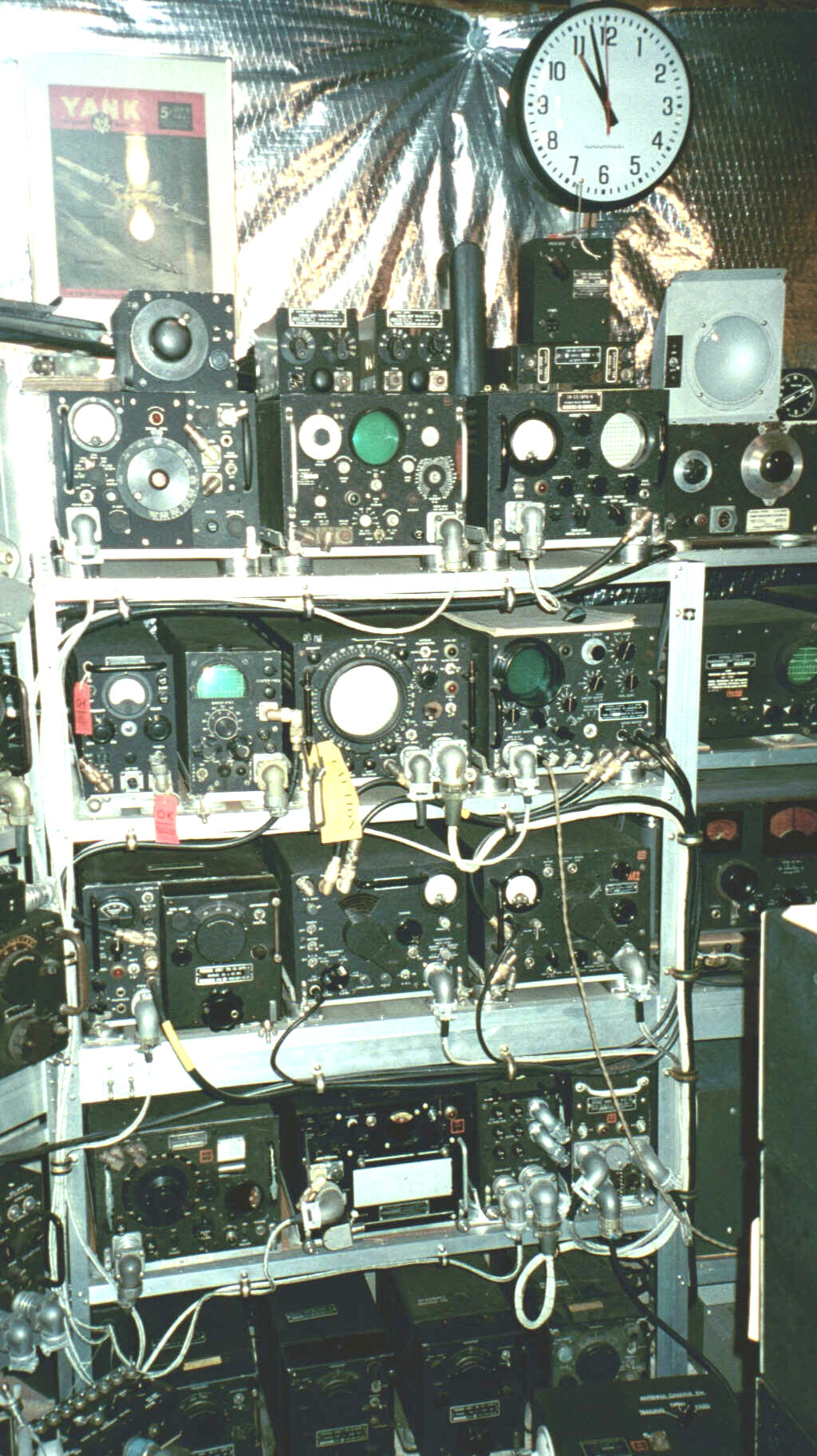
Radio countermeasures (RCM) went from infancy to amazing maturity during WWII,
including at least initial exploration of concepts that were well beyond the
technical and packaging capabilities of the day. Many of these concepts have only been realized
operationally since the the advent of integrated circuits. Shown here
are a few of the surveillance equipments used to acquire, record, and
analyze German and Japanese communications and radar activity.
On the top row at the far left (neglecting the small items sitting on top) is an
APR-5 receiver (1,000-3,000MHz, later extended to 6,000MHz
and called the APR-7). In the center is an APA-11 signal analyzer, and to its right is
an APA-6 signal analyzer with its companion
O-10/APA-6X oscillator. The APA-6
set was an early militarization of a basic oscilloscope and the well
known Hewlett Packard 200 series audio oscillator of the late 1930s, the latter used to generate
Lissajous figures for precise determination of pulse repetition rates in
enemy radar. The O-10 version of the oscillator is extremely rare today - I have
found only two in twenty years of searching. The meter on the APA-6 was less than satisfactory, being
easily affected by noise from other received sources. The later APA-11 in the center had a built-in oscillator
to eliminate the need for two separate boxes that comprised the APA-6. Just visible to the right of this bay is
one dedicated to the panic year of 1942, before military countermeasures gear was developed. This year of
'catch-up' was marked by hastily mounted commercial gear that provided a critical gapfiller for the period.
The most common of these is detailed here.
Second row, left to right: The small box with the meter is the Navy ARD
receiver, a designation that was fourth in the last Navy airborne receiver series (before the introduction of the A/N system)...ARA, ARB, ARC...etc.
Arguably the world's worst "production" receiver, this base unit was combined with a slotted line mounted on a
stub antenna to search for signals in the 300-3,000MHz area. Use of the slotted
line for more than 30 minutes was guaranteed to make one's arm drop out of its
socket, especially since it was intended to be installed with its antenna
sticking out of the fuselage at a 45 degree angle, forcing the operator into a
half crouch to tune it. To its right is an APA-38 panoramic adapter for use with the
APR-4 search receiver directly below it. The drawer pull handle is almost always missing from this unit. If you need one,
you can see a drawing I made to fabricate mine at APA-38 pull
assembly. Next comes an APA-17 direction finder display, used
with a rotating antenna and a variety of receivers for pinpointing
signal source locations. The display is similar to a PPI radar scope presentation.
Finally, there is the APA-10 panoramic adapter, used with the ARR-5,
ARR-7, and APR-4 or APR-5 receivers. This early "spectrum analyzer" had switchable IF frequencies of 455kHz,
5.25MHz, and 30MHz, but the 30MHz IF frequency required manual sweeping with the large silver
knob at the top of the front panel.
Third row: The APR-4 receiver is another one of those long-lived
designs, beginning life before the war as the General Radio P-540 test receiver. The P-540 morphed into the Navy ARC
and ARC-1 (in the series ARA, ARB, ARC, ARD, etc. mentioned above) before becoming the AN/APR-1. The USAAF took the APR-1 and improved it,
eventually nomenclaturing the result as the AN/APR-4. The APR-4 was used well into the 1960s in US aircraft
and went on to be a mainstay in a number of smaller countries around the globe. It
used five different plug-in units with a motor driven sweep ability to cover 38 to 4,000MHz,
making it extremely versatile for its time.
To the right of the APR-4 are repackaged
Hallicrafters receivers, the ARR-7 (basically an SX-28A,
tuning from 550kHz to 42MHz) and ARR-5
(an S-27/36 bridge technology, covering 27MHz to 140MHz). They both had an added isolation stage to reduce
local oscillator radiation back through the antenna, making the repackaged versions less worthy than their
antecedants in terms of noise, but a low noise figure wasn't a prime requirement for the target signals. Early in the war,
the stock SX-28 and S-27 were simply mounted on shocks and loaded on board ferret aircraft, (see
Early ECM surveillance equipment)
but the extra weight of the all-steel receivers and non-standard (for aircraft) physical configuration
forced a repackaging and a certain amount of redesign, like eliminating the high fidelity audio section.
The front-end circuit improvements were eventually introduced
into the standard receivers as well, causing them to pick up new model numbers - SX-28A and S-36.
Fourth row: At the left is a receiver that was so far ahead of its time
that it almost didn't see operational use due to production problems.
The APR-2 was a motorized fast frequency scanning receiver that covered
the range of 90 to 1,000MHz at 6 sweeps per second! It recorded the
presence of signals along with time information on thermal paper visible
in the upper right hand side of the panel, along with a panoramic
indication of frequencies on the rotating front dial. It was intended
to be used unattended in a fast pursuit plane like the P-38 or Mosquito
for quick and dirty searches of enemy territory for signals of interest.
To its right is the more elaborate APA-23 thermal paper recorder,
designed to work with a variety of receivers, though it was most
commonly used with the APR-4. Finishing off the row is the PP-85/APA-17 power
supply for the APA-17 DF display, and to its right a PP-32/AR power supply for the
ARR-5 and ARR-7 Hallicrafters receivers.
At the very bottom of the photo is a row of four plug-in tuning units for the APR-4.
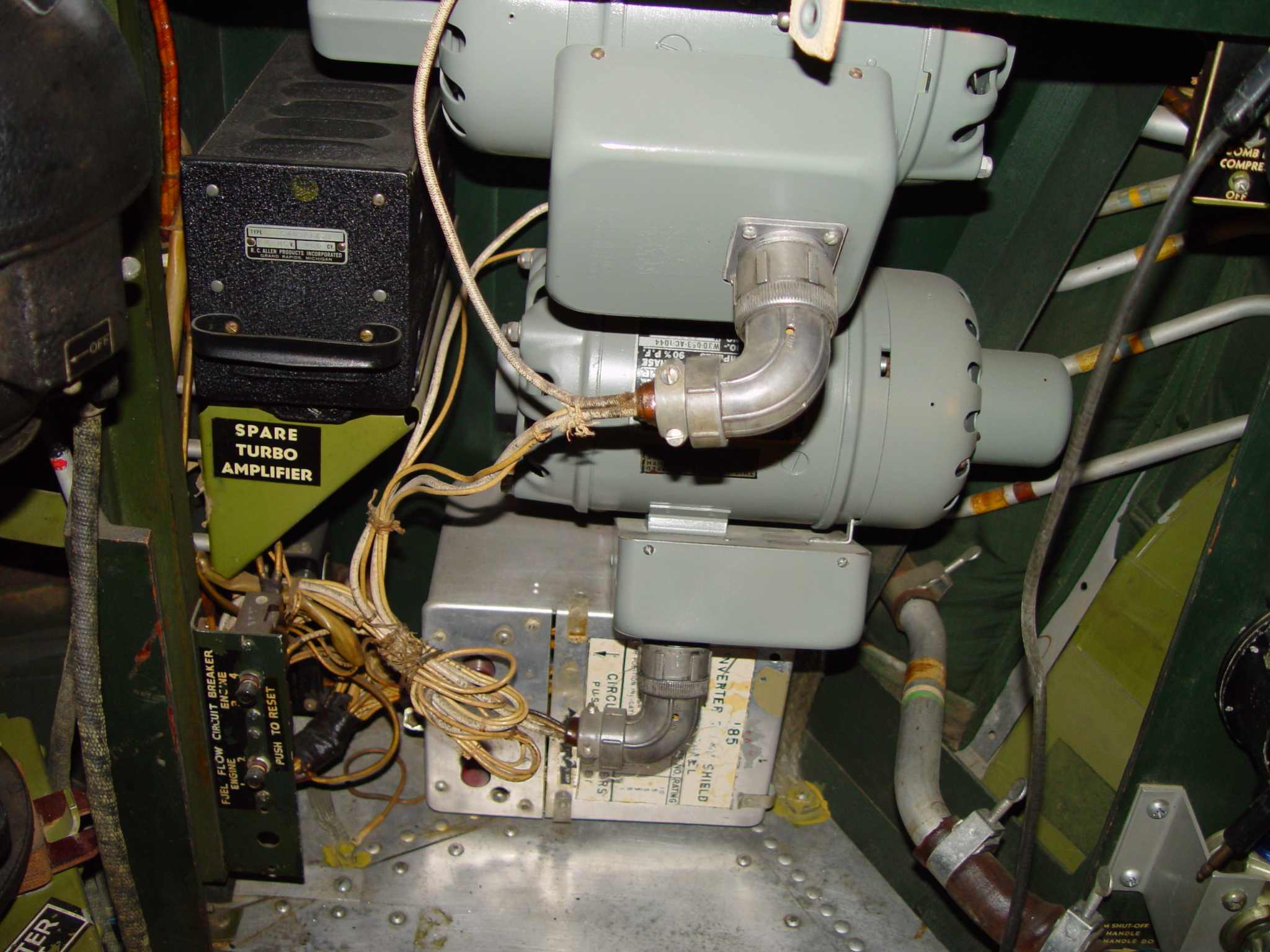
Finally, unseen behind the APR-4 tuning units is a pair of MG-149 rotary inverters that were more or less the standard general purpose inverters used in USAAF aircraft until after the war, when larger three phase units began to be introduced. The MG-149 was used as a sort of POP (point of presence) conversion capability and provided 115 volts AC at about five amps of 400 Hz power. The photo below shows a pair in the Enola Gay.
Return to AAFRadio
 Radio countermeasures (RCM) went from infancy to amazing maturity during WWII,
including at least initial exploration of concepts that were well beyond the
technical and packaging capabilities of the day. Many of these concepts have only been realized
operationally since the the advent of integrated circuits. Shown here
are a few of the surveillance equipments used to acquire, record, and
analyze German and Japanese communications and radar activity.
Radio countermeasures (RCM) went from infancy to amazing maturity during WWII,
including at least initial exploration of concepts that were well beyond the
technical and packaging capabilities of the day. Many of these concepts have only been realized
operationally since the the advent of integrated circuits. Shown here
are a few of the surveillance equipments used to acquire, record, and
analyze German and Japanese communications and radar activity.