Overview
 There are few pieces of radio equipment that generate so much interest in
the ham radio community as the famed "command sets" manufactured by the Aircraft Radio Corporation.
The late WWII part of the series was nomenclatured as AN/ARC-5, and together with the earlier
variants (Navy ARA/ATA and the Signal Corps SCR-274N), provided the basis for many an amateur's first communications capabilities.
The initial prototypes for this set were designed in about 1935 and bear an uncanny resemblance to
the sets a decade later! The original ARC Type K
of 1938 (currently in storage at the Smithsonian) has a configuration essentially identical to the more modern ARC-5 suite.
There are few pieces of radio equipment that generate so much interest in
the ham radio community as the famed "command sets" manufactured by the Aircraft Radio Corporation.
The late WWII part of the series was nomenclatured as AN/ARC-5, and together with the earlier
variants (Navy ARA/ATA and the Signal Corps SCR-274N), provided the basis for many an amateur's first communications capabilities.
The initial prototypes for this set were designed in about 1935 and bear an uncanny resemblance to
the sets a decade later! The original ARC Type K
of 1938 (currently in storage at the Smithsonian) has a configuration essentially identical to the more modern ARC-5 suite.
Strangely enough, I never intended to build this set into the "flight deck".
Like many folks, I started in radio
with an ARC-5 receiver and transmitter, and thought that it was too common to include, but the little beggars
seem to grow on you. After a steady if halfhearted accretion through several years of hamfesting, there were too many parts of
the set on the storage shelf to ignore...thus was born this dedicated bay in the rig.
Actually, the set pictured here is not quite the entire suite. Believe it or not, there are a few
pieces missing in the picture, either because of almost identical variations of a component,
or because they are located elsewhere. It reflects the sometimes daunting task
of finding all the parts of this prolific system and connecting them in a useful
way for amateur service. There are a number of "close" duplicates like the C-39
and C-48 control boxes, or the J-16 and J-22 jack boxes, which differ by only an
internal mike relay or other minor differences. In these cases, only one of the
close duplicates was chosen for installation. Also left out because of room is
a short series of early 6" modular rack mount control boxes which foreshadowed
the back-lit aircraft control boxes used today. A cantilevered panel up high
on the left side of the bay where the earphones are now hanging is planned to support them. In addition, in the summer of 1944 ARC
produced a short run of tunable VHF sets for Navy evaluation that were intended to augment the growing move for command radios to support VHF.
That set is described in some detail here.
The intent with these pages is not to dwell exhaustively on the general ARC-5
design or more common pieces...they are covered on a number of other excellent
web pages. Instead, the focus here is on some of the less often seen items
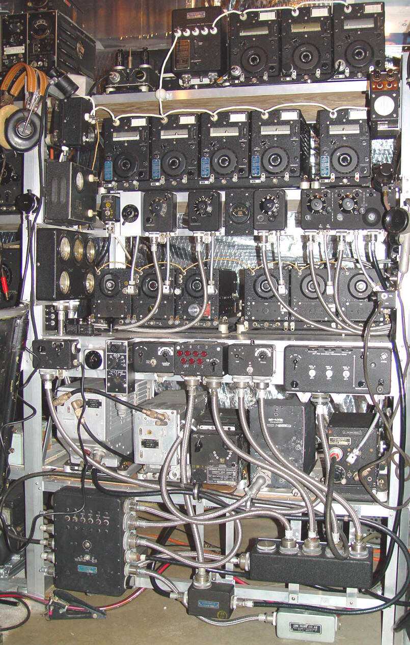
that were a part of the set. This photo provides a panoramic view to set the stage
for more detailed looks at the set and its peripherals on related pages.
The ARC-5 has come to be a generic term for the "command sets" originally designed
by the Aircraft Radio Corporation in the late 1930s but in fact, of the three flavors
of these sets, the ARC-5 seems to have been
procured in large quantities only by the Navy. The one exception is the Western Electric VHF
set that actually started off the ARC-5 series in 1942 (T-23/ARC-5 and R-28/ARC-5). That suite was used by both
the Navy and the AAF, and there are both Navy and Signal Corps contract numbers on examples
I have seen. Other than that set, I have yet to find one with a Signal
Corps contract number. Another possible exception to dual Service deployment may be
the R-23A MF receiver, an improved version of the original R-23 that was used as a range
receiver by both Services well into the 1960s. In any case, the photos to the left and elsewhere
on this website offer a reference in some photographic detail of the alternatives available on the
WWII ARC-5 contracts.
On the top row, from left to right, the major ARC-5 components in the photo are:
O-4/ARC-5 spot tune crystal oscillator (and immediately behind it, an MD-7 modulator),
TN-6 MF loading coil, T-15, T-16, and T-17 transmitters on an MT-73 3 transmitter rack
and MT-72 shock mount. A closer view of this row and the row below can be seen
here.
Second row: RE-2 antenna relay, T-18, T-19, T-20, T-21 transmitters on an MT-75
4 transmitter rack, and a T-22 transmitter on a single MT-69 rack. The scope to
the right is a mysterious modulation monitor with an ARC-5 seven pin connector,
transmitter antenna post, and knobs - a lost ARC-5 component? A closer view of this is
located on the transmitter page.
Third row (mostly control boxes): A-61 dummy load (an unusual Boonton made version), C-27 spot tune control,
C-25 remote ant/loop switch, C-26 single receiver control, another C-26, an I-71A
remote antenna current meter, another C-26, and finally a C-43 HF/VHF receiver control.
Fourth row: ARC 7507 transmitter meter panel, R-26 (spot tuned to 3885kHz,)
R-23, R-24, R-25, R-26, and R-27 receivers, J-22 jackbox. The transmitter test panel
had a receiver equivalent (also with five meters), but only the transmitter panel is actually
useful in monitoring normal operation of the sets. A closer view of this row and the row above can be seen
here.
Fifth row (more control boxes): C-48 auxiliary control, field mod channel
selector for the C-131/AR autotune mechanism (below in sixth row,)
pilot's remote control box for ARB (shown in ARC-5 installation manual), C-29 HF transmitter control,
C-30 VHF/HF transmitter control, C-30A VHF/HF transmitter control (designed to replace the pushbutton type to its left
because of maintenance problems), and C-38 master (audio) control box.
Sixth row: T-23 VHF transmitter, R-28 VHF receiver,
C-131/AR autotuned R-26M 6 channel adapter,
AM-40/AIC-4 interphone amplifier, and AN/ARR-2 homing
receiver.
Last row: J-17A system junction box,
J-28 VHF/HF control junction box,
another mysterious junction box with no label, and bottom right, an
F-5/AR
28v power filter. Another uncommon junction box is not shown here, the
J-34,
used to split transmitter control box outputs to allow control of two separate transmitter racks. Its use wasn't essential - the
functionality could be replicated in the field through a "Y" cable splice - so the expense evidently resulted in very low procurement numbers.
Just a brief note on JB-** junction boxes - not all junction boxes needed for a large ARC-5 installation were an
official part of the set. Numerous junction points for interphone and power wiring were also needed and
were considered part of the particular airframe. For example, the Navy had a series of generic boxes
(NAF 1128-*) that
had angled tops so that they offered a 45 degree bend possibility (in addition to the usual 90 degree geometry)
for any cable/conduit that was required to connect to it. The various sizes had NAF
part number suffixes and were extensively used throughout the aircraft. The USAAF was fond of both metal and plywood junction boxes,
(One of these plywood versions can be seen here near
the bottom of the page).
Closer views of many of these parts can be seen at the other ARC-5 links on the
flight deck in the ARC-5 Forever series.
Some of the tools and fabrication operations required to make components for this and other WWII sets are in the
Garaj Mahal part of this web page.
Return to Flight Deck