
There is a switch on the antenna changeover relay for both the original Navy ATA and later AN/ARC-5, as well as early models of the SCR-274N command transmitters, that permits a remote "cockpit mounted" antenna current meter to augment the local RF ammeter on the relay. The remote meter was an option marketed by Bendix for their late 1930s commercial airline transmitters, and is displayed in some of their prewar product brochures. By the time their 1941 brochure rolled around, the meter (described as an MT-33 in their curious nomenclature system) was only listed for the small TA-6 transmitter.
Like so many of the Bendix products, this meter was adopted for use by both the Navy and Signal Corps for a variety of applications, including the "command" sets. In addition to the local/remote switch on the antenna relay, a connector on the side of the transmitter racks provides connectivity for the meter in the ATA and ARC-5. The early SCR-274N sets had provision for the remote meter as well, with the connector being located on the lower edge of the BC-451-A control box. The remote meter is shown in the 1941 SCR-274N maintenance manual, in the section describing Test Sets RC-54-A and RC-55-A. However, both the connector and switch were removed from that set fairly early in the contract series and the reference deleted from later 274N manuals.
No specific part number reference to the remote meter is made in the command set manuals, other than to say that the remote meter is not part of the contract, although the US Army version of this meter, the I-71-A and B, is specifically called out in the documentation for the ill-fated SCR-240 transmitter (the BC-338) that was supplanted by the SCR-274N under less than honorable conditions because of miserable design and performance. Similar anomalies abound in the documents of the time - such peripherals were more often associated with a particular airframe than a specific radio - but at least one pub (Signal Service, Air Service Command, Airborne Radio Equipment Handbook dated 24 APR 1943) does have a photo of the I-71-B meter and identifies it as being for the SCR-274N, so by that time general USAAF usage had perhaps dropped down to that last remaining set.
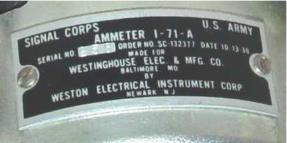
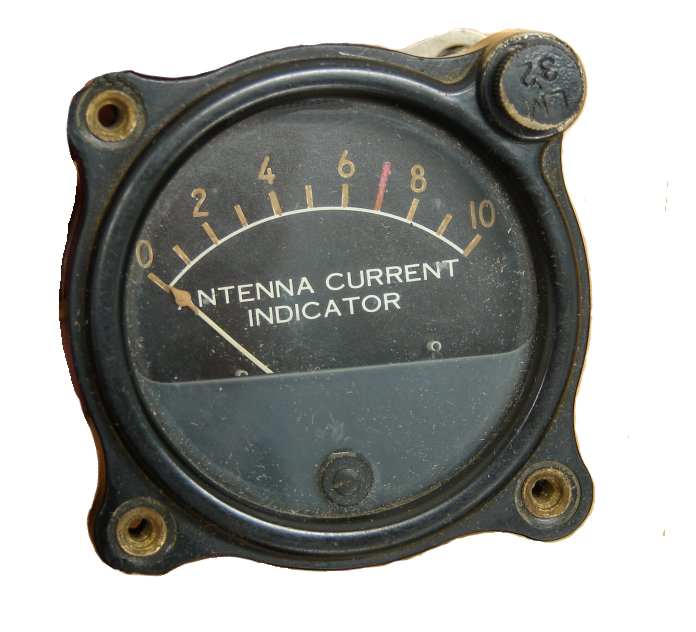
The particular I-71-A sample above was made by Weston in 1938 for Westinghouse, who made the GO-* and GP-* aircraft transmitters used by the Navy (among many other products), while the I-71-B was made for the Aircraft Radio Corporation. Note that there are no specific ampere values on the meter face of either version - it is intended to be used for relative readings only, primarily during tuneup - the same caveat extended to all the "0 to 10" command set RF ammeters on the antenna relays. Full scale indication is actually in the rough area of 4 amperes or so - same as the presumably more accurate meter installed in the A-61-A dummy load. This meter must be used with an external thermocouple (another reason for not having any numbers on the face - being an "add-on" accessory, it could not be selectively matched with a particular thermocouple as other sets frequently are.) The only meter deflection guidance available in documentation is in the SCR-274N test set diagram mentioned above, which suggests that the meter "reads approximately half scale on CW" when used with the five ohm A-61-A dummy load.
Never very widely used, the rush of war made crew specialization a necessity, and allowing pilots and other non-radio crewmen to have the ability to fiddle with transmitters ended up being an undesirable concept anyway (even if it only amounted to optimizing the trailing wire antenna length by watching the meter and flipping the reel motor one way or the other). As it turned out, it was even a bad idea to let them tune the receivers from their flight positions - pilots and copilots especially tended to tickle perfectly good settings off of assigned frequencies and then complain about lost comms and receiver "failures" after they returned. As a result, the use of the meter gradually devolved into 1) simply an indication to the flight crew that the transmitter was putting power into the antenna, an overly expensive tool for that purpose, or 2) a technician's tool to test or tune up a radio in any aircraft that had the antenna relay remote from the transmitter. Because of the low installation frequency, very few of these meters have survived.
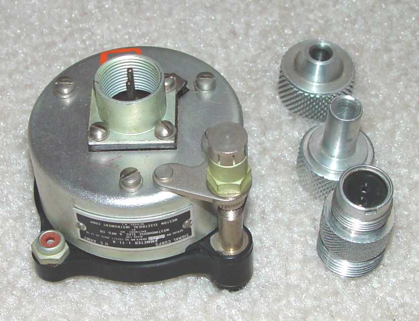
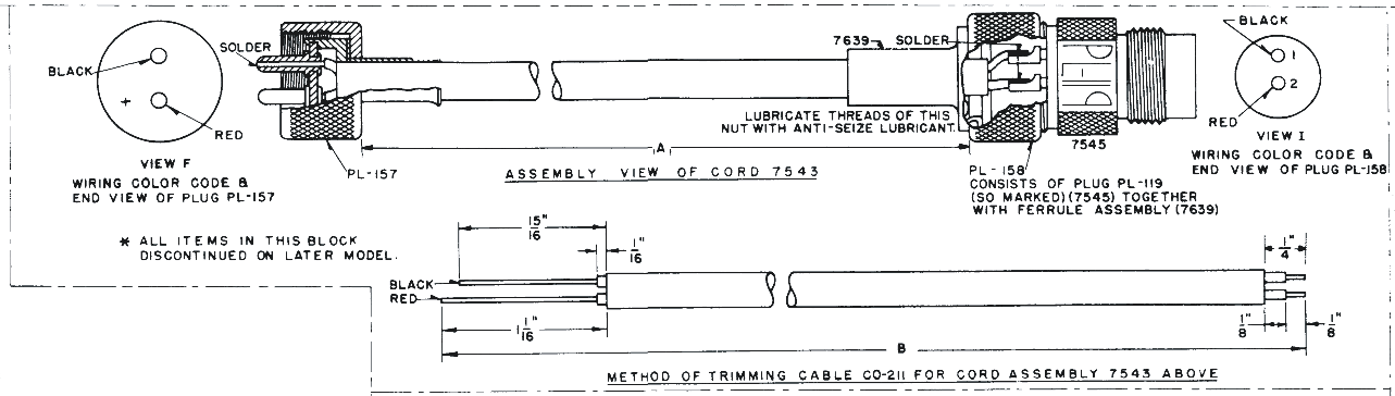
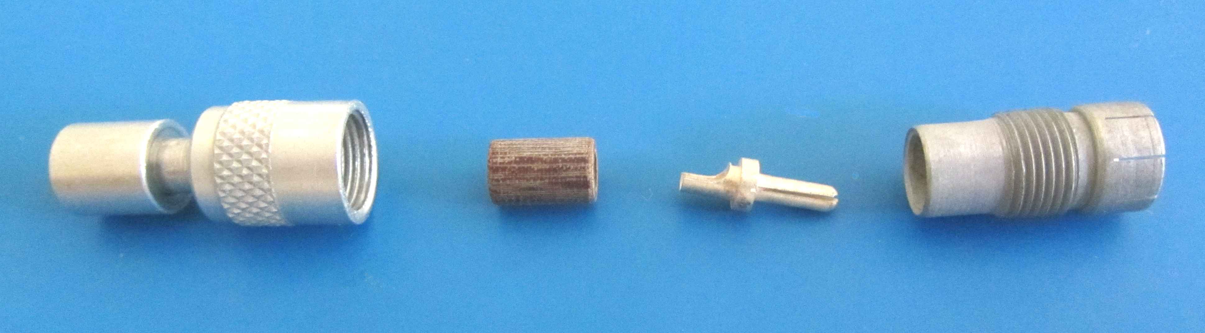
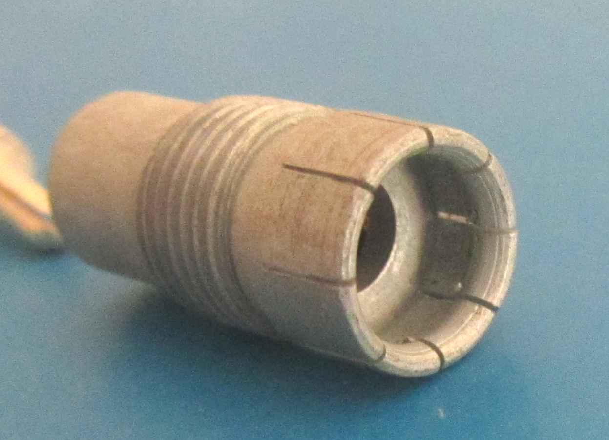
The photo above shows the rear of this indicator, along with the uncommon PL-119 two pin connector...one of the accursed Plessey/Breeze externally threaded connector styles apparently beloved only by a few Bendix and/or military navigation equipment designers and of course our British cousins of the era - but evidently universally disliked by anyone who had to actually work with them in the field. During installation, the aluminum shell spins around the bakelite insert, which is hopefully held stationary by side forces from the small pins in the chassis mating connector - a concept that was evidently never thought all the way through the vagaries of dried-out lubricant, sand, and general grit from the runways and flight lines of the world. No keyway is provided, so fitting the two connectors together in a dark corner filled with the usual cables, aluminum struts, and support angles (grunt...mmmff... blast!) is problematical at best. Two different backshells were used for these connectors, shown at upper right. In the peculiar math of the Signal Corps, the backshell at right center (an ARC #7639), when screwed onto the basic PL-119 connector at lower right, makes the assembly into a PL-158 assembly, supposedly correct for the I-71. The basic connector accommodates open-wire or conduit feeds, though many open-wire USAAF (and Navy) installations using these types of connectors later in the war dispensed with the backshell altogether. One of the reasons for this apparently sloppy practice is that the basic aluminum connector shell must rotate with respect to the wire bundle in order to install the connector into its chassis mounted socket, somewhat defeating the purpose of an integral backshell in providing any significant strain relief. It essentially forces the use of a clamp type backshell that can be retightened after connector installation. (Reference dark corner description above...)
The staff at the side of the meter is a sleeve for mounting one of the tiny 3 volt LM-32 lights that most Bendix navigation control boxes use for backlighting a dial or meter. Happily, there is a commercial number for the LM-32 light that can occasionally be found with a search - GE 323, or sometimes 323 mini - but the prices vary all over the place. These days, it is generally a good idea to keep the power supply below 2.5 volts to extend the life of these increasingly rare bulbs.
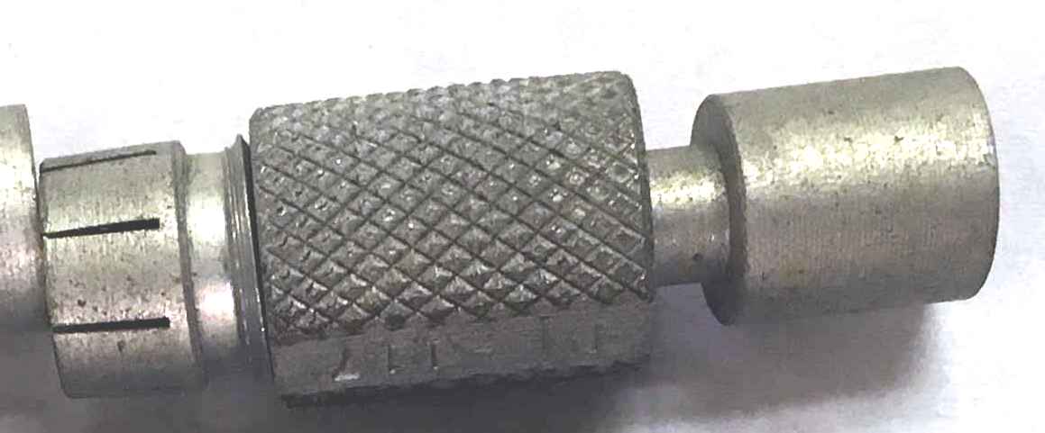
There is a cap over the end of this staff on this example that must be discarded when a bare braided shield single conductor wire is connected. The connector used for this connection is unusual enough to merit a closer look: It is a peculiar looking "push-on" connector with the nomenclature PL-117 - about as rare as the PL-119. Why a braided shield wire? Most likely because one of the 3 volt sources back in the day was a 3 volt winding on either a vibrator supply or a 400 Hz ballast transformer for UV cockpit lights - both RF noise introducers to radio control boxes. The PL-117 was used in the late 1930s for these low voltage instrument lights, but in later WWII equipment seems to have been discarded in favor of stud and solder lug (for internal meter lighting, which rapidly diminished with the use of UV lights in the cockpit). It at least has the advantage of not needing to determine indexing to install and remove. Just pop it on or off.
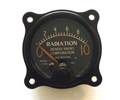
Finally, just to round out the list of WWII-ish "remote" cockpit antenna meters, there is another one which was produced by Weston for Bendix equipment. I picked up this odd little item below from a hamfest table as a curiosity, not knowing at the time what set it supported. Recently I discovered it was a part of the Bendix TA-2J series of aircraft transmitters as an optional component. I was vaguely thinking nuclear radioactivity at the time I first saw it, but of course it is simply an arbitrary 0-10 scale for antenna voltage picked off by a resistance divider and rectified by a 6H6 duodiode in the transmitter. It actually only provides an uncalibrated indication of RF voltage presence on the RF output connector, not antenna current like the Bendix MT-33 remote antenna current meter mentioned above does. Why Bendix introduced this particular type of remote indicator instead of just offering the MT-33 is lost in the mists of time, and the fact that it never received an MT-** number seems odd as well. Perhaps it was derived from contract specifications by the British..."radiation" sounds more like a Commonwealth term than U.S. military parlance, which tends to be more like "RF Output", or some variation. I suppose sometimes it's good to know there is at least RF power being fed to the antenna, but a simple voltage indication wasn't a very common feature in aircraft transmitters.