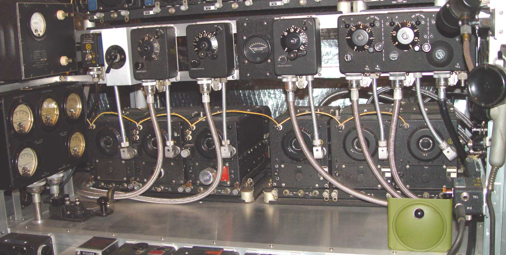
The reason for an extra receiver in this lineup is that the one on the far left is an R-26 set up in a "spot tuned" or "lock tuned" configuration, an approach that prevented any remote tuning ability from within the aircraft. Its C-27 control box is at the upper left of the line of control boxes in the photo above, and the receiver is currently spot tuned to 3,885 kHz.
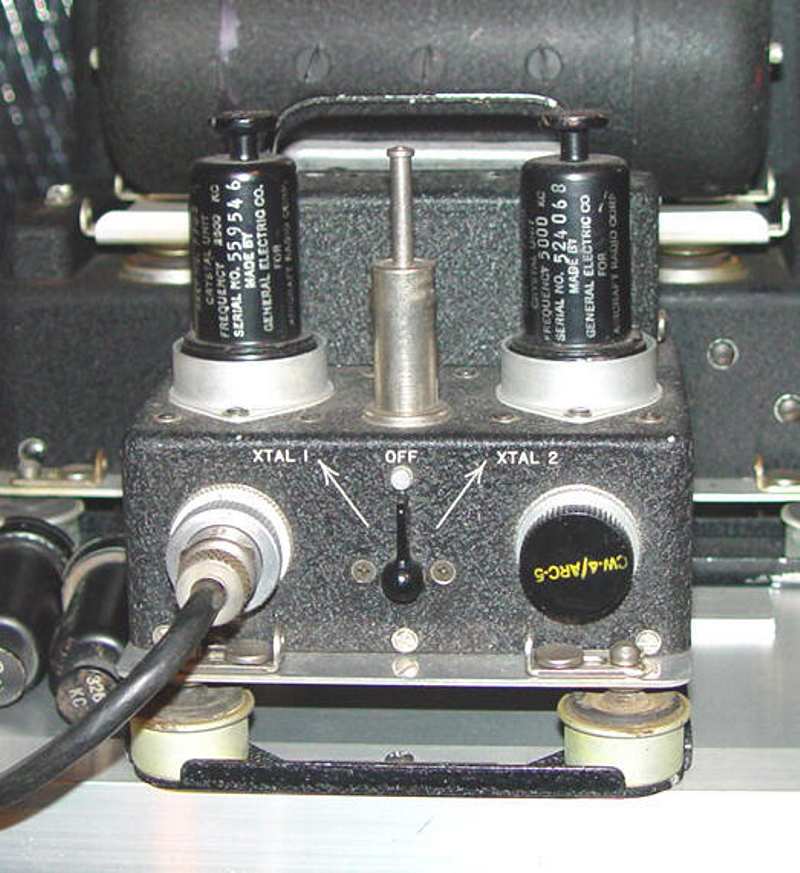
So, why was this particular configuration created? It seems that WWII pilots were notorious for having little patience with their gadgets, and temporary loss of signal due to fading or the like was often met with attempts at retuning the radio, usually ending up off the assigned frequency. There were times when this loss of communications led to tragic results. To counter this temptation, ARC added temperature compensation and stabilized the local oscillator on the R-25, R-26, and R-27 HF sets, so that once tuned to a particular frequency by a ground technician it could be locked in place until the next mission. The technician used either a stable signal generator or the O-4/ARC-5 crystal oscillator to set this frequency. See photo below for a closeup of this oscillator. It operated with a plate voltage of 28 volts DC - the small sleeve at center is the antenna, so no direct connection to the receiver was required. The cable on the left is for 28v power, while the capped connector on the right permits remote selection of either crystal when needed so that the oscillator could be mounted permanently in an aircraft. I have never seen any evidence that one was used in that way, but it's entirely possible that it could have been. The crystals that were in this oscillator when I received it were 2,500 kHz and 5,000 kHz - not standard tactical frequencies to be sure.
One of the less common accessories for the O-4 was a set of six crystals, shown below. The frequencies were primarily those of the calibration crystals in the transmitters, with a couple of exceptions. Here is the list:

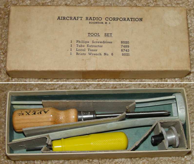
Speaking of uncommon accessories, ARC actually assembled a small tool kit for the command sets. In the original 1939 Navy RAT and RAV receiver contracts, each complete set was actually delivered with the kit. With the SCR-274N Army contract, the kit could be procured with the RC-54A and RC-55A test set, though the choice of tools is somewhat puzzling. The note on this Army Signal Corps drawing is interesting - "Articles to which this note applies were procured per Specification RE-13A-597A, of the Bureau of Ships, Navy Department, as modified by exceptions thereto covered by Notes of the contract." The Army kit added a 6743 local tuning control, likely because the original Navy contracts in 1939 were delivered with receivers having local controls as a standard feature.
The tube extractor is the same type used in the General Electric RAX-1 receiver triplets (but with an ARC part number of 7489). The circular end is slipped over the tube and the handles are squeezed to contact the side of the tube. Because of the deceptively high pressure you can exert with the handles, this puller is dangerous to use with glass tubes - it's pretty much intended for a metal receiving tube application, which restricts it to the command receivers. The receiver local tuning knob seems like a good choice as well, but the criticality of the Bristo wrench and Phillips screwdriver eludes me, unless they were simply not part of the standard techician's tool bag.
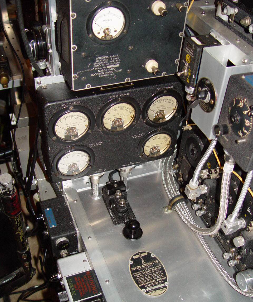
The ARC-5 stabilized receivers were marked with a yellow inked "S" inside a circle on the front panel. A special control box, the C-27, was produced and was intended to permit the air crew only the luxury of setting RF gain and audio on/off. (The latter switch was probably needed...the instructions for adjusting the gain states "Set for maximum tolerable noise"...) Remember there was no squelch control on these sets, so atmospheric noise in the headphones between transmissions was a fact of life. The C-27 also contains a rotating disk behind a window on which a channel number is printed, but it has no electrical function. The mission frequency can be marked on the top of the control box in pencil for the particular mission. See photo below - the C-27 is to the right of the A-61A dummy antenna. For some reason, not many of these control boxes survive, suggesting that they had not been deployed in any significant numbers by the end of the war.
The particular A-61A dummy load here is sort of a quixotic protest against an otherwise uniform CBY-manufactured suite of equipment in the ARC-5 bay, though ARC was originally owned by Boonton Radio in the 1930s. This variation has cooling louvers in the side and appears more robust internally than the more common Western Electric models that are usually seen. (The oval Boeing tag is from a crashed B-29A on Guam ca. early 1945 - a gift from a friend for the "flight deck...")
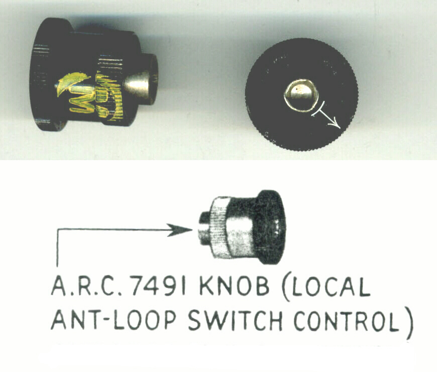
To the right of the C-27 is a C-25 loop/fixed antenna switch control lever, connected mechanically to either the R-23 or R-24 by the same type of flexible spline cable used for tuning the receivers. This control is actually a holdover from the older SCR-183/283 and RU receivers. There was also a control knob available (the ARC #7491) that screwed directly onto the receiver loop switch, similar to the local tuning control knob. See photo below.
Both of these loop switch controls are pretty rare, for the simple reason that these two receivers were not commonly used as DF receivers associated with a loop antenna. You will find more details on these two controls (including fabrication details) located HERE. There were no technical shortcomings that prevented it, but more specialized sets in the larger aircraft were developed for that purpose, and smaller aircraft either flew with the larger planes or used the radio range system. The R-23 was designed to be used primarily with that radio range system, which provided "pathways in the sky" through special transmission techniques, while the R-24 was intended as an outboard set for homing and ILS systems. No nomenclatured loop antenna was ever produced for the ARC-5 set beyond some proposed prototypes in the ARC labs (which later did result in a loop option for the commercial ARC Type 12 and 15 models). Without AAF or Navy interest except for emergency loop operation, there was no demand to manufacture the peripherals in any quantity.
Of the five sets, apparently only the R-23 saw modifications significant enough to warrant issuing an -A suffix. Modifications to enhance listenability and AGC action were made, along with using plastic coated wire rather than the earlier fabric covered rubber. The R-23A is the most common of the MF receivers, probably because it saw a long lifetime extending well into the 1960s.
Moving to the right in the top picture, there are three C-26 single channel tuning control boxes in a row, broken only by another uncommon bird - the I-71A remote antenna current meter. The I-71 is one of those pieces whose reason for existance makes your head feel fuzzy. In the historical progression of command sets - from the Navy ARA/ATA, to the SCR-274N, to the AN/ARC-5 - only the ATA and ARC-5 antenna relays always had a switch to choose between local and remote meters. For a brief time at the beginning of production, the SCR-274N sets also had them, but they were eliminated fairly early in the contract history. The paradox is that nowhere in ARA/ATA or ARC-5 literature is there any hint of a remote meter being available to actually make use of their capability. Only with the SCR-274N is there any evidence of the existance of such a meter (as a part of a test configuration diagram), and even then there is no indication of it actually being installed in any aircraft. The conclusion seems to be that the capability might have been used for testing purposes, but that's about it - this despite the fact that the meter is a standard four screw aircraft panel meter with provision for internal lighting (through an unusual 3v bulb used with Bendix navigation control boxes). Even the two pin connector mounted on the rear is an oddball - from the series of internally threaded connectors most often seen on the Bendix navigation sets like the ARN-7. On the ATA and ARC-5 sets, the interconnecting cable must be plugged into the two pin connector on the left end of the transmitter rack rear junction box. In the brief appearance on the SCR-274N sets, the connector is located on the lower edge of the BC-451 transmitter control box. Naturally, this is not the same connector as on the meter end - it's a refugee from the older RU and GF command sets. Each end of the cable was evidently designed by different committees...
Last but not least in the control box row is a C-43/ARC-5, a fugitive from the Western Electric VHF ARC-5 predecessor - the BC-942 receiver and BC-950 transmitter. Originally designated the BC-944, this control box allows control of two HF receivers, as well as audio from the T-23/R-28 VHF set often installed with them. A C-5 UV lamp used to illuminate the controls at night partially blocks the VHF side of the box.
Finally, along the bottom row is the entire suite of R-23, R-24, R-25, R-26, and R-27 receivers. The R-24 (third from left) is the broadcast band receiver, and was sometimes used in conjunction with the ZB-* and AN/ARR-1 homing receivers, as well as ILS systems. The junction box in its front was designed to provide power to the homing receiver or other peripherals. The olive drab painted circular device at lower right is another receiver, or at least it is identified as such in the military nomenclature. This "Receiver, Ash," is an ashtray used in all the Boeing aircraft from 1936 until the 1950s. More on these and other ashtrays is located here.