The Transmitter Set
Shown below is the entire suite of 8 MF and HF transmitters in the AN/ARC-5 set.
Frequency ranges, along with the most common calibration crystal frequencies, are listed below.
(Be aware that the SCR-274N and Navy ATA sets had different "standard" crystal frequencies.)
While these seem to be the most common, with the exception of the T-15, T-16, and T-17 they do not
match the recommendations in the maintenance manual to use the top end of each respective transmitter
band for a crystal check frequency. The reason for the exception is lost in antiquity.
T-15 500-800 kHz (Calibration crystal 800 kHz)
T-16 800-1,300 kHz (Calibration crystal 1,300 kHz)
T-17 1,300-2,100 kHz (Calibration crystal 2,100 kHz)
T-18 2.1-3.0 MHz (Calibration crystal 2,604 kHz)*
T-19 3.0-4.0 MHz (Calibration crystal 3,265 kHz)
T-20 4.0-5.3 MHz (Calibration crystal 4,435 kHz)
T-21 5.3-7.0 MHz (Calibration crystal 5,505 kHz)
T-22 7.0-9.1 MHz (Calibration crystal 8,870 kHz)
*other frequencies sometimes found for this crystal appear to be 2,601 kHz and 2,609 kHz.
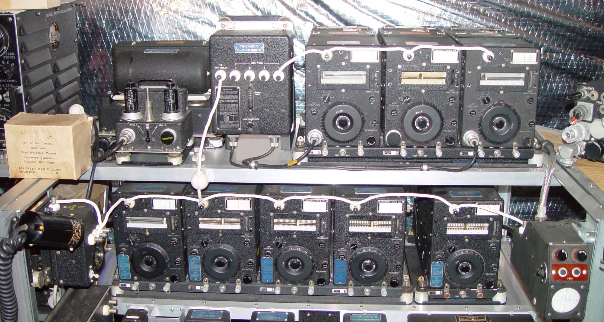
Starting at upper left in the photo above is the O-4/ARC-5 crystal oscillator that was used for
setting the later "lock tuned" ARC-5 receivers to a predetermined mission frequency. A close-up of this unit
and more about its purpose is on the ARC-5 receiver page. To its
left is a box of six crystals that was packaged for its specific use. Behind
it is an MD-7/ARC-5 modulator, used with all of the ARC-5 transmitters to provide power and modulation.
To the O-4's right is a TN-6/ARC-5 MF antenna tuner, followed by the T-15 and T-16 transmitters to its
right. The T-17 finishes off the top row, all three transmitters sitting on an MT-73/ARC-5 rack supported by an MT-72/ARC-5 shock mount.
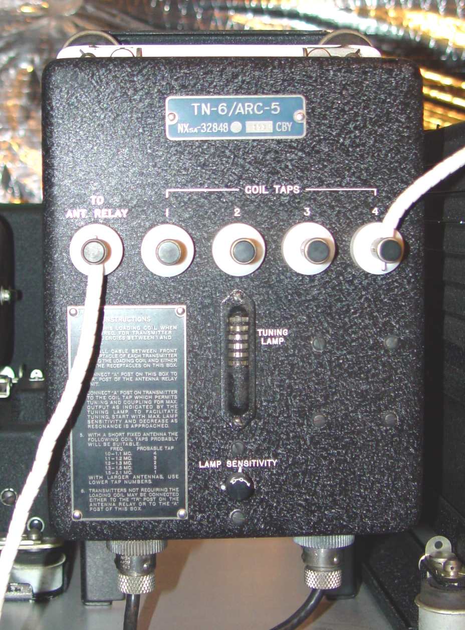
TN-6/ARC-5 antenna loading coil
This loading coil was used with electrically short antennas to allow tuning of the final stage in the MF transmitters.
It reflects the considerable reuse of older components that was ARC's SOP - the small grille guard for
the neon lamp is from an earlier GF-** transmitter control box.
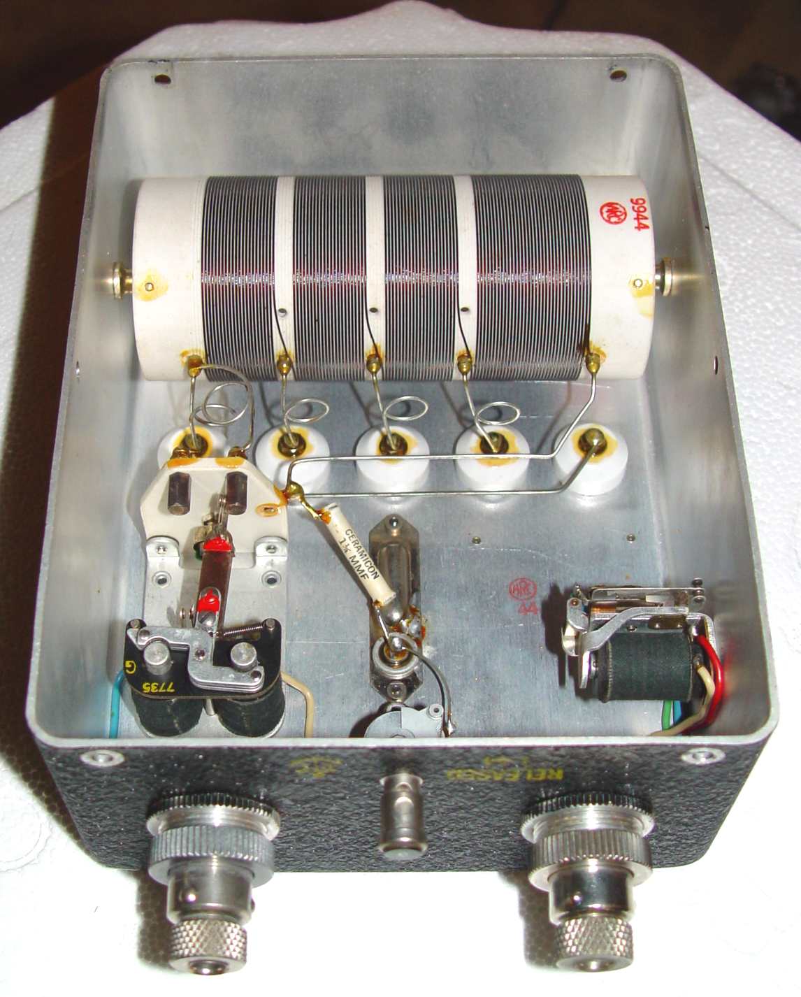
TN-6/ARC-5 antenna loading coil interior, showing typical ARC attention to detail in design and finish
There is some degree of controversy over the employment of these three MF sets. The most credible explanation to date in my
mind is that they were used with the float planes stationed for reconnaisance on the tails of the
battleships - this from two veterans who were there. The use of MF (500-2100kHz)
was apparently geared toward the numerous available receivers covering this range
on board in the various radio rooms within the ship. Other theories include air to ground
applications and small ship comms. There are probably more ideas kicking around
out there, but no "smoking gun" documentation as yet.
The second row in the top photo contains the RE-2/ARC-5 antenna relay on the far left, followed by the five common HF
ARC-5 transmitters. The left four are supported on an MT-75/ARC-5 four transmitter rack, held up by an MT-74/ARC-5 shock mount
sporting the firmest, tallest 1" diameter Lord shock units I have ever seen on a piece of ARC-5 equipment. On the far right is a
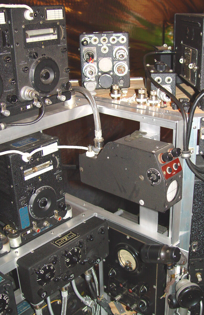
modulation monitor oscilloscope that originally came from an AN/APG-15 radar set. I initially offered an MFP flavored lollipop
to anyone who could identify its antecedents, but only received one correct answer, considerably depleting my stock of two lollipops.
See photo below for this mysterious concoction. The braided shielded cable leads to a power supply and audio from the modulator
to obtain the classic trapezoid image shape.
Return to ARC-5 page