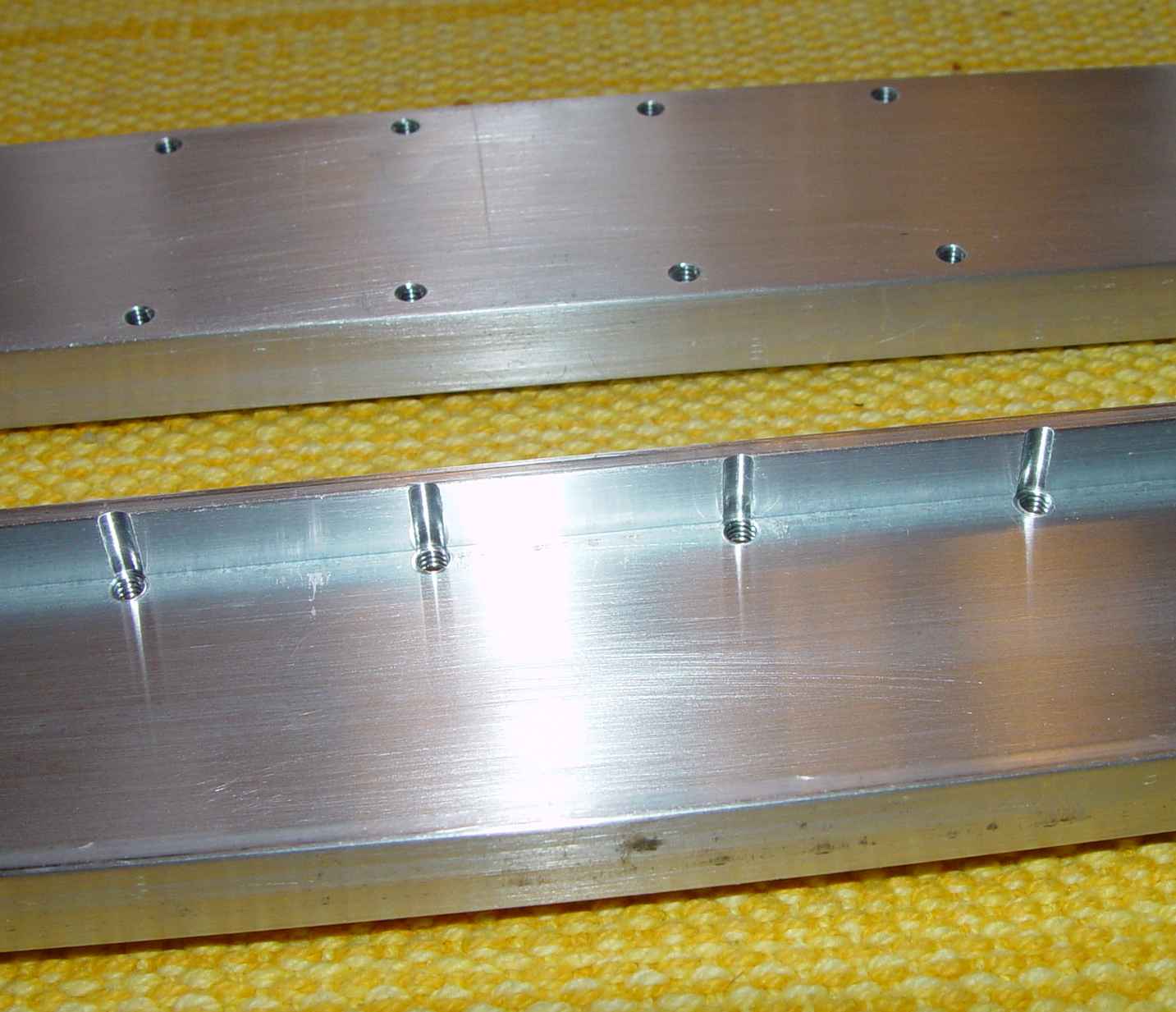
Closeup of bottom of 2" channels
In one of my idle moments a few years ago, I made a dimensioned sketch of where and how many holes I would have to drill to mount the three Navy RAX-1 receivers that I had managed to find. Not only is there a total of 48 locating holes to be drilled, but trying to line them up ran into the reality of the chairs being so far under the racks as to frustrate any attempt at marking the holes in place. I finally decided that the only practical way to do it without shouts of "Oh No!", and verbally abusing otherwise innocent holes that wandered off center, was to use the same approach I used with the ARB/ATB pair of sets. Often in actual WWII practice, similar mounting rails were simply spanned between other support rails that made up an entire avionics equipment mounting structure in the aircraft, but a pair of rails can also be used to mount on a flat board or flat piece of other material.
Although the need to make a pair of these rails was overtaken by acquisition of the original XRAX set, which had its own spanning rails built into its rack, a question about the problem from a friend evoked the need for another "twenty minute job"*
Since I had already drawn up the dimensions needed for spacing the receivers an inch apart per the manual and had a spare six foot length of 2"x1/2" aluminum channel leaning up against the wall of of the shop, what could be simpler? Saw it off, drill a few holes, and voila!
Now, after spending the better part of forty years in engineering for the DoD, I am well aware of the term that brings fear to project leaders - the dreaded phrase "mission creep". Sometimes it is because of unforseen conditions, sometimes "to make things better". That always seems to happen with my projects as well, and this was no exception. The first complication came when I laid a mounting chair on top of the two inch wide channel. Hmmmm...exactly the same size. Gee, those mounting holes look a little close to the edge...but...well...oh, I'm sure it'll be okay (I said to myself in a burst of optimism). Quickly cutting off two pieces of channel and milling the ends to achieve a length of exactly 27.500" (okay, it might have been 27.502 for all I know - it's the thought that counts), I proceeded to lay out the drilling pattern. After drilling the four end mounting holes, I screwed the two pieces together back to back and clamped them in the milling vise. Hmmm again...looks like a small arc of the 1/2" leg of the channel will need removal to keep the drill from drilling a crooked hole. Oh well, it's too late now. I don't have any wider channel and I've already cut the aluminum and drilled four holes. Using the same excuse that has sent me down many a longer road than getting the right material in the first place, "I am already committed" (he said heroically) as he turned to the milling cutter drawer and fished out a 3/16" end mill. It turned out the end mill had super honed knife edges and managed to slice my thumb. Grumbling all the way to the medicine cabinet, I spent another ten minutes cleaning and bandaging the thumb. I note with a certain amount of satisfaction that I have already exceeded the twenty minute "estimate" of the entire job.
What happens next is pretty repetitious - spot drill the location hole with a center drill, then drill the hole through both pieces using a drill that doesn't touch the side of the channel (luckily, that works out to be the same size as a #8 screw tap, which makes me immediately decide to tap the holes, since I began to wonder how in the world my friend was going to manage attaching 48 tiny nuts to the bottom of the channels anyway. (mission creep...creep...) Then, without moving anything, I chuck the little end mill and bore down to the flat surface of the channel web, creating those clearance scallops you see in the bottom view below. Dial the table over to the next position on the chart. Repeat. Flip the channels over, and using the tap drill to quickly locate each hole, counterbore the scallops in the other channel.
Now it's been a while since I used the tapping head in the milling machine, but I'm glad I didn't dispose of it. A tapping head takes a little setup work, but when the hole count gets above ten, it saves you a lot of time. It has a mechanism inside the head that allows you to start the tapping with a downward motion of the drill press handle to engage the tap in the workpiece, and when you are to the depth you want, you simply raise the handle and the tapping head stops the tap and reverses the tap rotation, allowing you to quickly back the tap out and then slide the part over for the next hole. Do 24 holes like that, and I'm finished. Note that this segment is the only part of this saga that is a twenty minute job! The remaining work left was to unbolt the two channels to deburr and wet sand the aluminum to remove defects.
*A euphemism often uttered by my bride when she wants me to do something for her, as in "It's only a twenty minute job, dear." One of those little twenty minute jobs eventually ended up taking three years to complete after all the change orders. Now that is mission creep!..
If you were starting these from scratch, obviously you could order 2-1/2" wide channel, or even more simply, 2-1/2"x 3/8" or 1/2" aluminum bar to avoid the scalloping operation.
Finally, below is a view of the entire set mounted in its equipment rack.
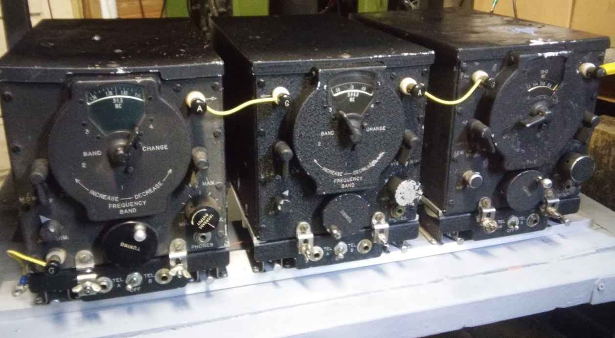
One of the advantages of mounting the receivers this way is the ability to move the whole set to another location with the removal of four screws.