The early versions
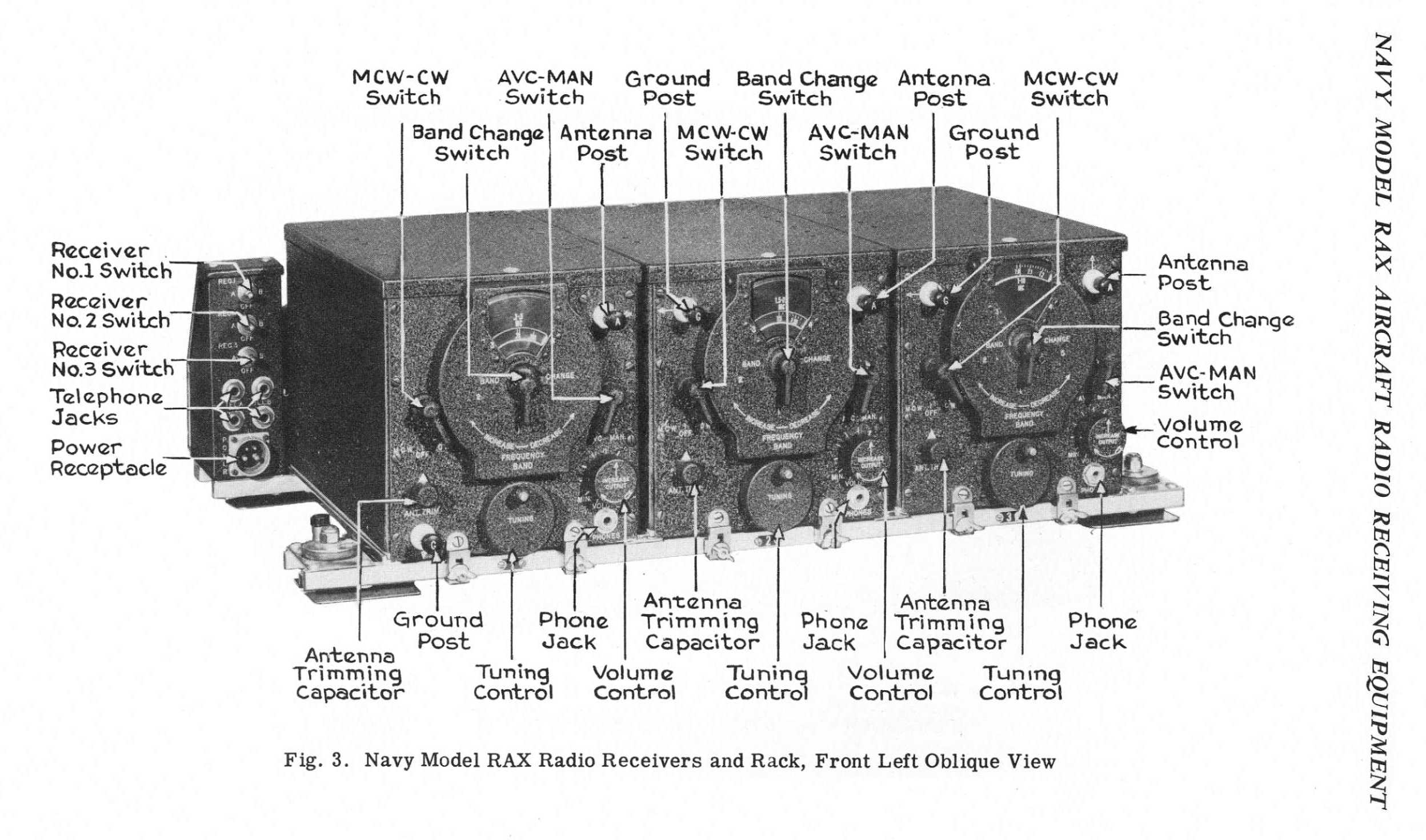
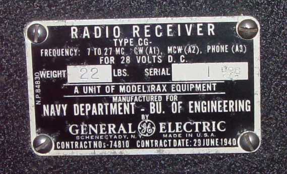
Below is the initial production configuration shown for the RAX set, serial numbers 1 through 75. The
"control box" for the set was mounted on the left end of the three receiver rack. Serial
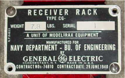
numbers 76 and beyond used the same receivers, but had a new single rack for each receiver and a separate
power junction box, with the combination relabeled the RAX-1. The switches for selecting "Tel. A" or
"Tel. B" were then mounted on the front of the single rack, similar to the practice on the ARC command
receivers.
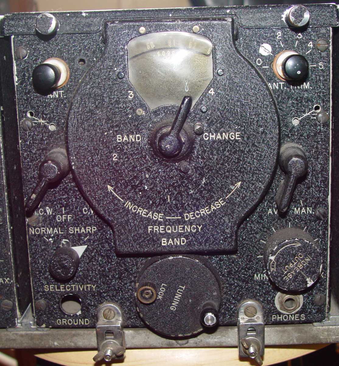
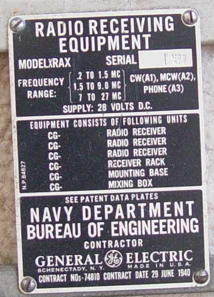
However, the developmental set (XRAX) has some interesting features not found in the production runs:
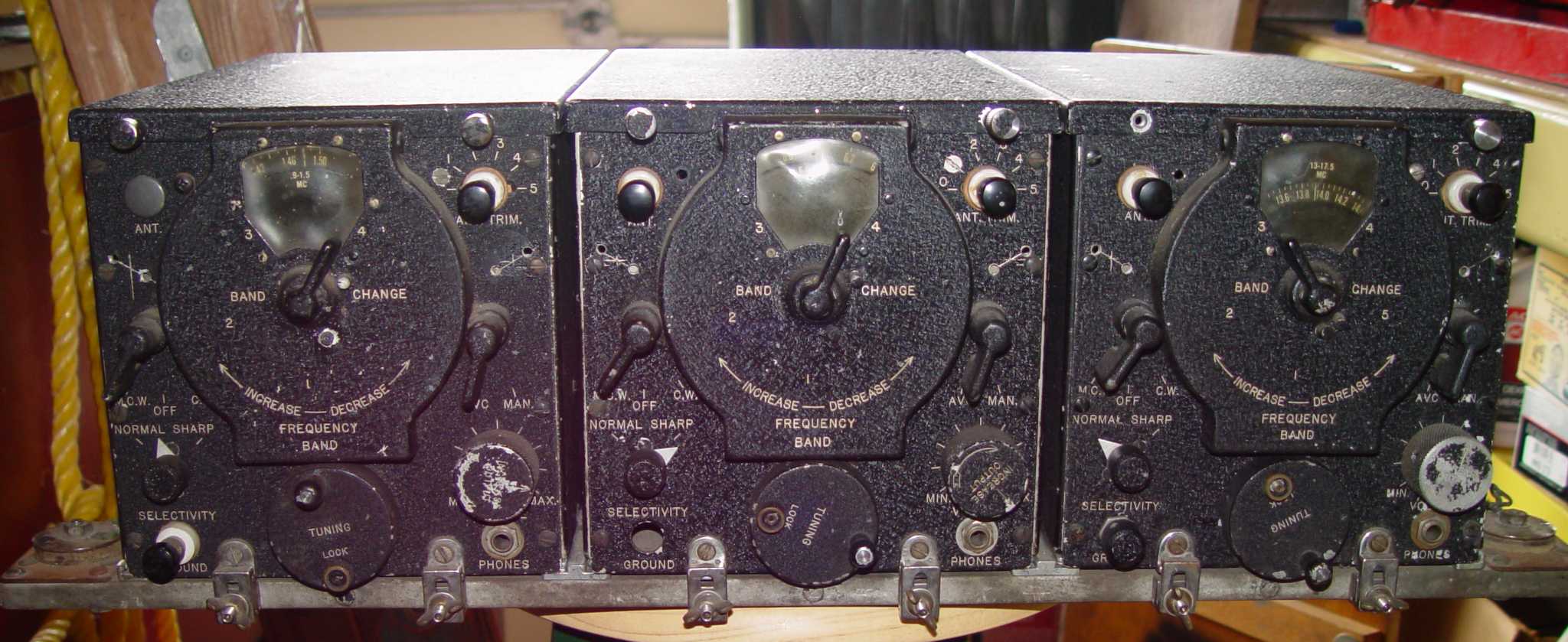
Notice the different cover retention screws, an added normal/sharp selectivity switch, and the tuning dial
lock, none of which were carried forward to the production sets. Missing from this set is a "mixing box"
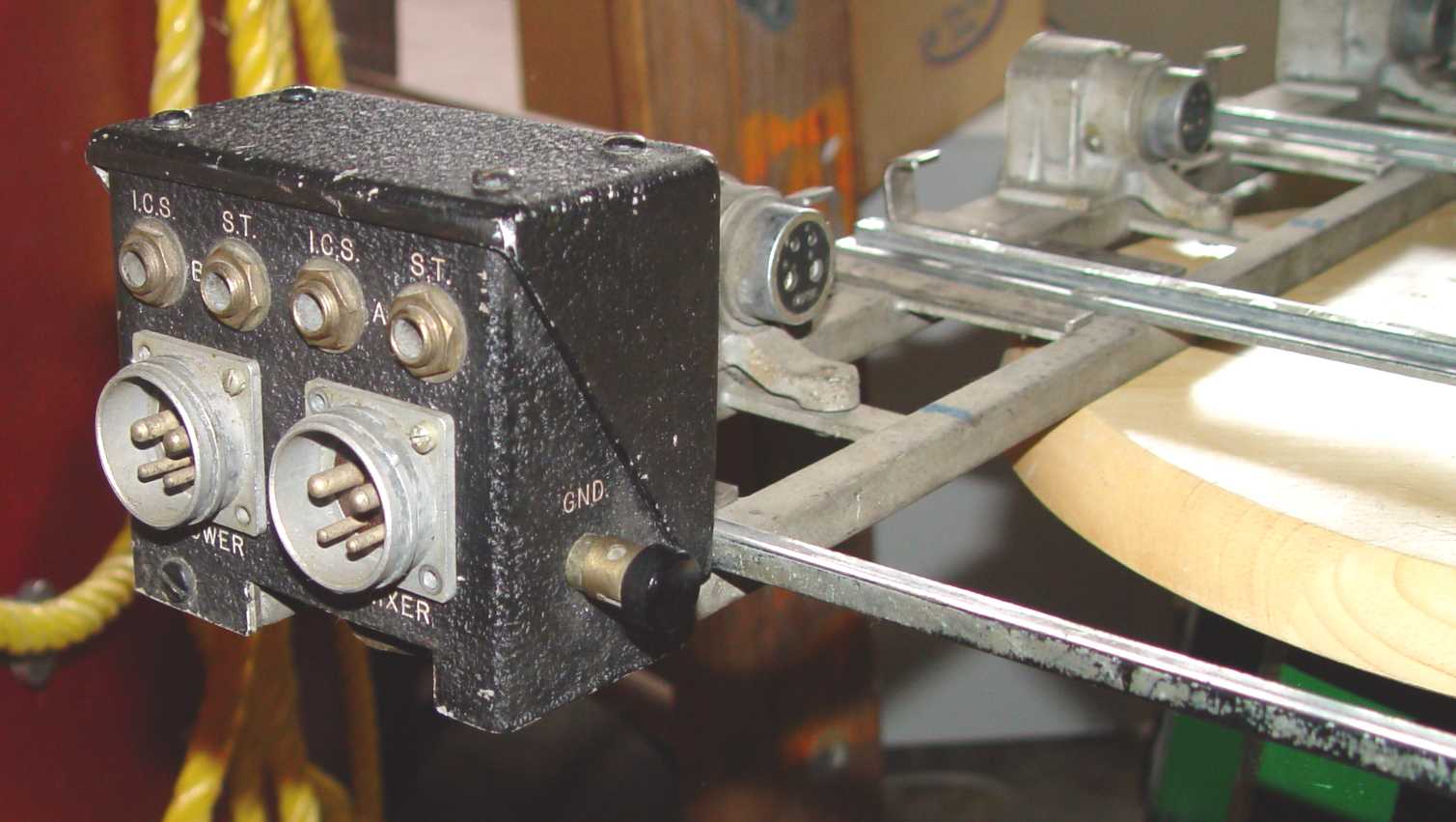
which evidently contained the three switches shown on the initial production rack at the top of this page. There are some
other anomolies, like chrome plated aluminum rails for the receivers to sit on, chrome plated compression
washers for the rubber shocks, and two junction boxes (one on each end) for the connections to the mixer box
and on to the aircraft interphone system. The chrome plated aluminum rails are a curiosity, since the plating
procedure for aluminum is much more difficult than for other metals. It may have simply been for looks,
however. The extraneous holes are the legacy of changes made in the process of reaching the final production
configuration, and is typical for a set that bears "X" in its designator (for experimental) and serial number
1 on its components. The familiar RAX antenna "daisy chain" has also evidently been through at least two different configurations.
Return to RAX-1 description