The forgotten element - Interphones
One of the common complaints heard from radio amateurs over the years about WWII aircraft equipment is that
they don't have enough audio gain. Given that they were never designed to drive a speaker, it's perhaps
not surprising, but I have seen extraordinary hacks on some equipment like command receivers and the BC-348
in efforts to solve the problem. In my mind, the solution for anyone supporting the idea of minimal
modification is to find an appropriate interphone amplifier of the period and use the radio to feed it.
There is a wide variety of these amplifiers that usually go begging on the market,
and using them permits the employment of their own fun accessories like jack boxes and the like. Beware, however,
that they can begin to take on a life of their own and form a significant collection effort in their own right.
One thing not well understood about the interphone amps is that up until about 1944 they were not generally used to
amplify the audio from receivers. The radios themselves were required to drive the multiple earphones of the crew
directly, and the amplifier was only used to amplify the microphone inputs. In effect, the amp simply provided
one of several audio sources for the various jack boxes to select. This deficiency in effectively using the interphone
amp power led to reduced volume whenever several of the crew switched their earphones to any single radio position
(to listen to Tokyo Rose on the Liaison receiver, for example.) Beginning with the AN/AIC-3, the number and
variety of audio sources had increased to the point where it made sense to begin feeding them (on a switchable
basis) to the interphone amplifier, along with the 'traditional' mic inputs. The subsequent WWII interphone
systems (the AIC-4 generally used with the ARC-5 system, and the AIC-5 described below) followed that philosophy. As a
result, to use the earlier Navy and USAAC/USAAF systems with your rig, some thoughtful if minor wiring changes from
the original manual schematic may be necessary, along with the addition of some ~10,000 ohm balancing resistors to
permit signal combining, similar to the approach shown here.
Some thought to switching may be necessary as well, if you want to use the amp for multiple sources. An example
of a minor redesign is shown in RC-36 manual excerpts. This
wiring change to a jack box allows the carbon mikes plugged into it to be amplified in the "command" switch
position to adequately drive the command set modulator to 100% without the usual shouting required. The original
microphone amplifiers in the three command set modulators don't normally have enough gain to accomplish this. With a level pot
added to the circuit, it will usually permit a range of carbon microphone buttons, even those which are somewhat
cemented by time and moisture, to be used effectively. (By the way, note that some are simply beyond amplification help.)
AAC/AAF amplifiers - just the basics
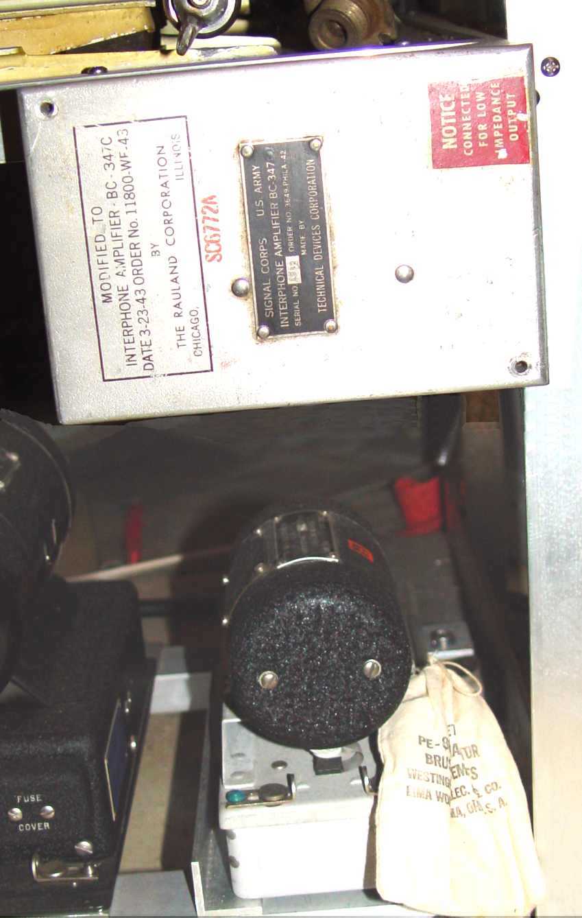 "Old Faithful", the BC-347 AAC/AAF standard in WWII. The PE-86 dynamotor to power it is below the amplifier.
Probably the most common of these interphone amplifiers is shown above, used in thousands of Army Air
Corps/Force aircraft. It comes with the PE-86 dynamotor below it for those locations that do not have
+250vdc available, but its simple, single tube design allows it to piggyback on the receiver power if necessary.
It was included as a part of a whole series of RC-* (Radio Component) systems, depending on the jack boxes
involved. By the end of the war, it was listed under Interphone installations RC-34, 35, 36, 51, and 175!
As a side note, not all the RC-* systems were interphones, by any means. The designator was used as a catch-all
for stray dogs and cats which didn't fit under a normal communications (SCR) nomenclature, like blind landing
systems, IFF, certain special radars, and other oddball equipment. The arrival of the Joint A/N naming
convention finally rationalized this confusing situation. A schematic and associated interphone wiring is
shown in the
RC-36 manual excerpts.
The primary jack box used with the BC-347 in the later aircraft was the
BC-366, but later variations like the
BC-1366, (with a VHF position included on the
selector switch) are perhaps more common. I have seen a number of variations of the later box, with VHF or UHF
engraved over the 'command' position.
*************************************************************************************************
Quite a few older AAC aircraft were fitted with the BC-212 interphone amplifier below. Essentially a
redesign of a 1930's amp with 1940 tubes, it was teamed with the 1930s jack boxes, like the
BC-213. It was a central part of the RC-15, RC-27, and RC-45 Interphone
Equipments, and shared some of the peripheral boxes for a time with the more modern BC-347 amplifier, like the BC-327, BC-334, and BC-345.
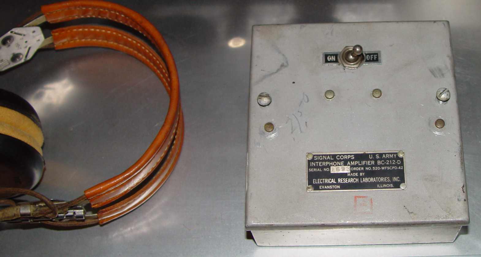 BC-212 amplifier
*************************************************************************************************
The Navy Interphone amps - Experimenters Inc.
For some reason the Navy went bonkers with these systems, almost giving the impression that a new system
was designed for every new aircraft. They assigned an RL-* desgnation to them, and only a couple of the more
common ones are shown below.
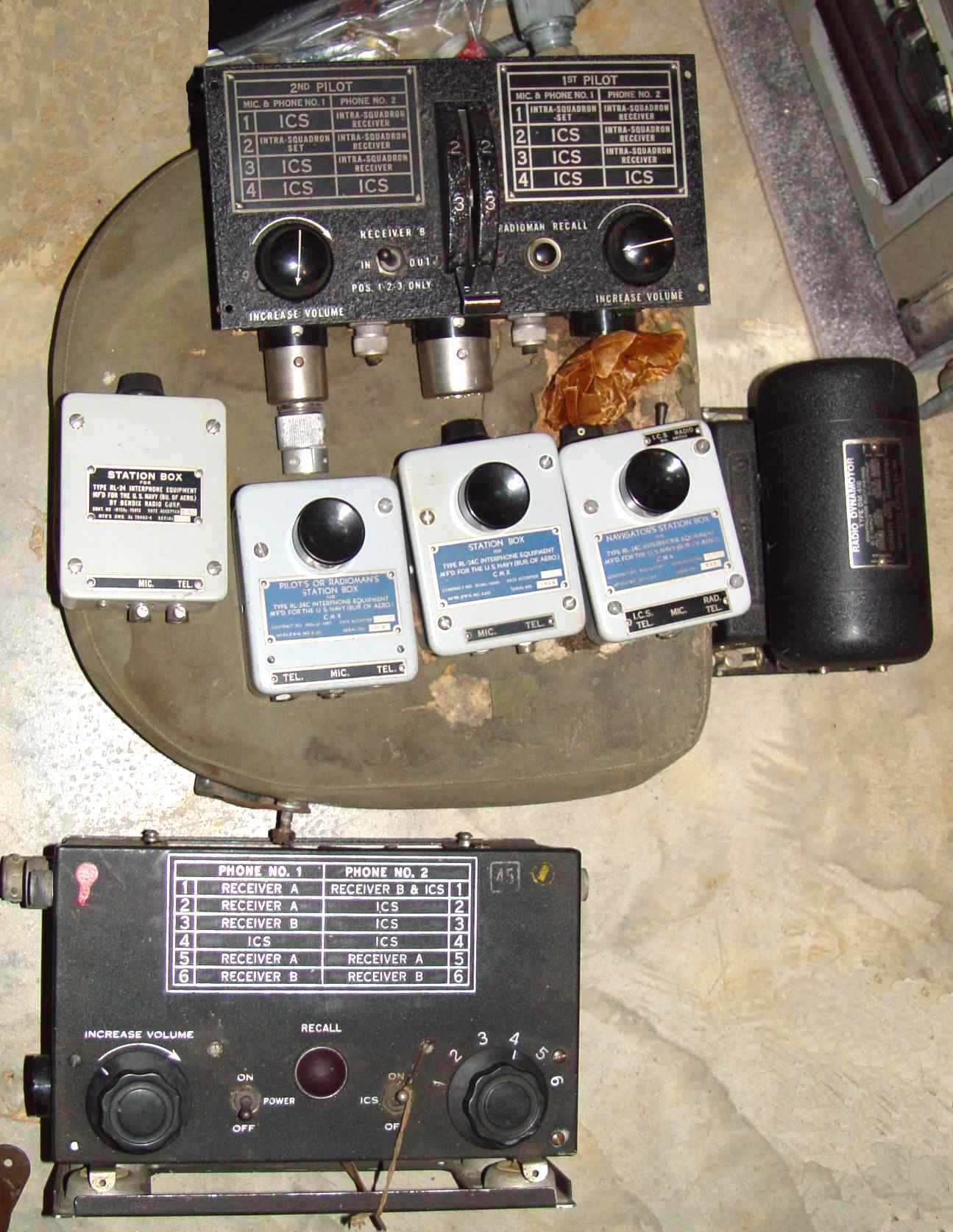 Navy RL-24
The unit above should probably get the award for 'most needlessly complex' (at least for that point in time.) There was a separate
part number and ID plate for almost every aircraft position jack box, like Pilot's, 2nd Pilot's (copilot), Navigator,
Radio Operator, etc., with minor variations like a volume control or ICS/radio switch. (ICS = Inter-Communications System,
a Navy-peculiar name for the interphone system.) It included two independent amplifiers, one for general crew application
and one for the key crewmen who needed to hear the radio(s), like the pilot/copilot and radio operator. The Navy was fond
of giving certain crewmen (like the radio operator) independent earphones, each side plugged into a different source,
though it must have driven the wearer slightly nuts at times. However, it was prescient in providing the flexibility
later needed for larger, more specialized flight crews. More on this is discussed in the
Earphones and Headsets page.
*************************************************************************************************
 Navy RL-7 and one of its associated jack boxes
A more measured approach was the RL-5, 6, 7, and 9 series above, all minor variations on a capability that would
later be reflected in the AAF contracted AN/AIC-2 below. These had rear mounted dynamotors rather than the
separate mount dyno like the RL-24, so they were self contained. The large six pin plug in the center was
to supply other equipment like an LM frequency meter if desired. Strangely enough, the station boxes didn't
have a Navy nomenclature number - just a manufacturer's drawing number that varied according to the particular
vendor involved.
*************************************************************************************************
The later Interphone amps - the A/N systems
Beginning in 1943 a uniform nomenclature system was introduced to identify equipment, and the interphones
were assigned an "AN/AIC-*" identification prefix. Shown here are three variations on that series.
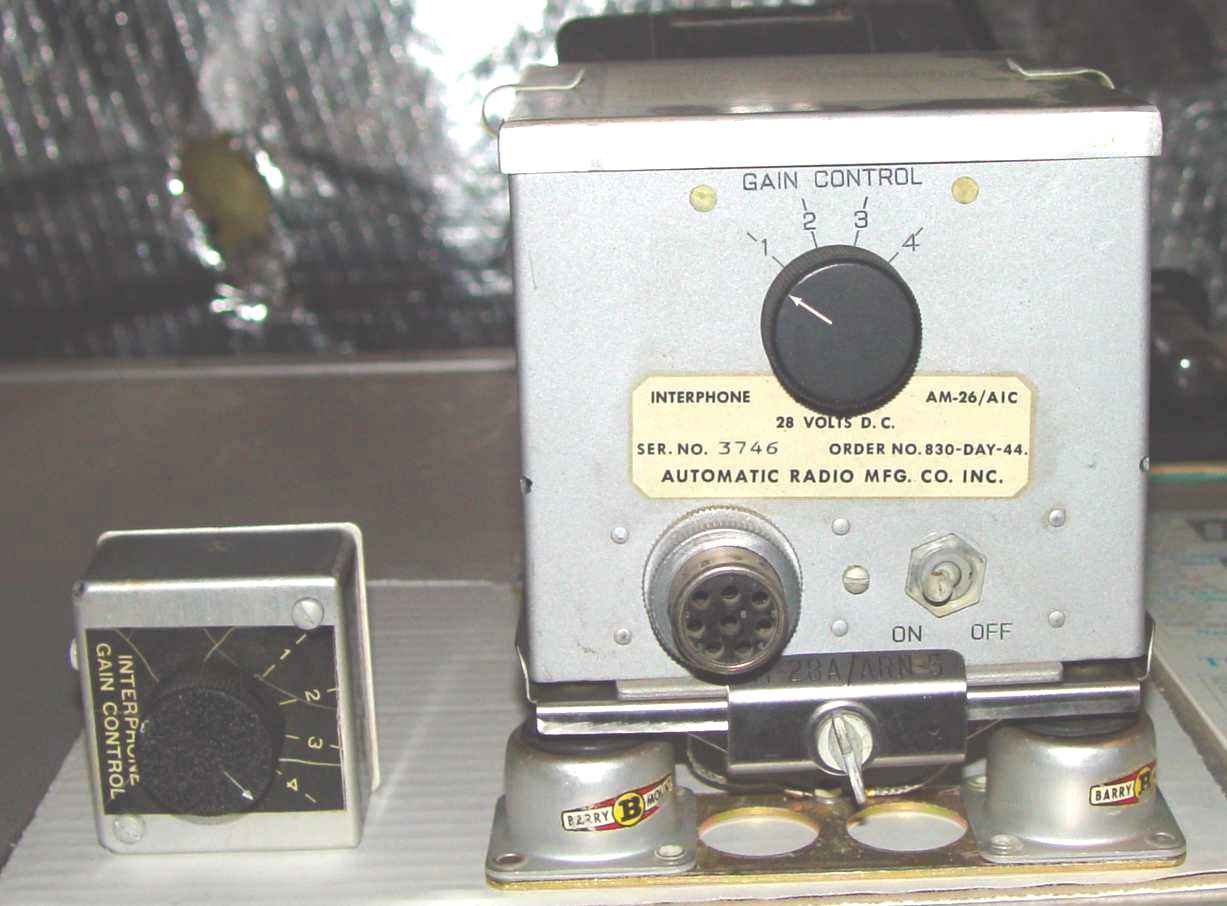 AM-26/AIC-2 amplifier on its MT-28/ARN-5 shock mount and C-97/AIC-2 remote volume control
This amplifier was the late 1944 replacement for the old BC-347, and included enough power to drive
interphone systems in aircraft with ten or more crew members, a task that in part was a failing of the BC-347. It was
one of the few pieces of equipment that tried to lower costs by using another set's shock mount - in this case from the
AN/ARN-5 ILS system. An integral rotary gain control switch, with the optional C-97/AIC-2 remote control head shown here,
allowed the radio operator to increase the gain with increasing altitude to counter the loss of "loudness" in the thinner
air. In the AM-26A/AIC, a set of three manometers was added to automatically switch in more gain above 10,000, 20,000,
and 30,000FSL, a practice that was continued in all the later aircraft interphone sets.
A complete manual for the system is located here.
*************************************************************************************************
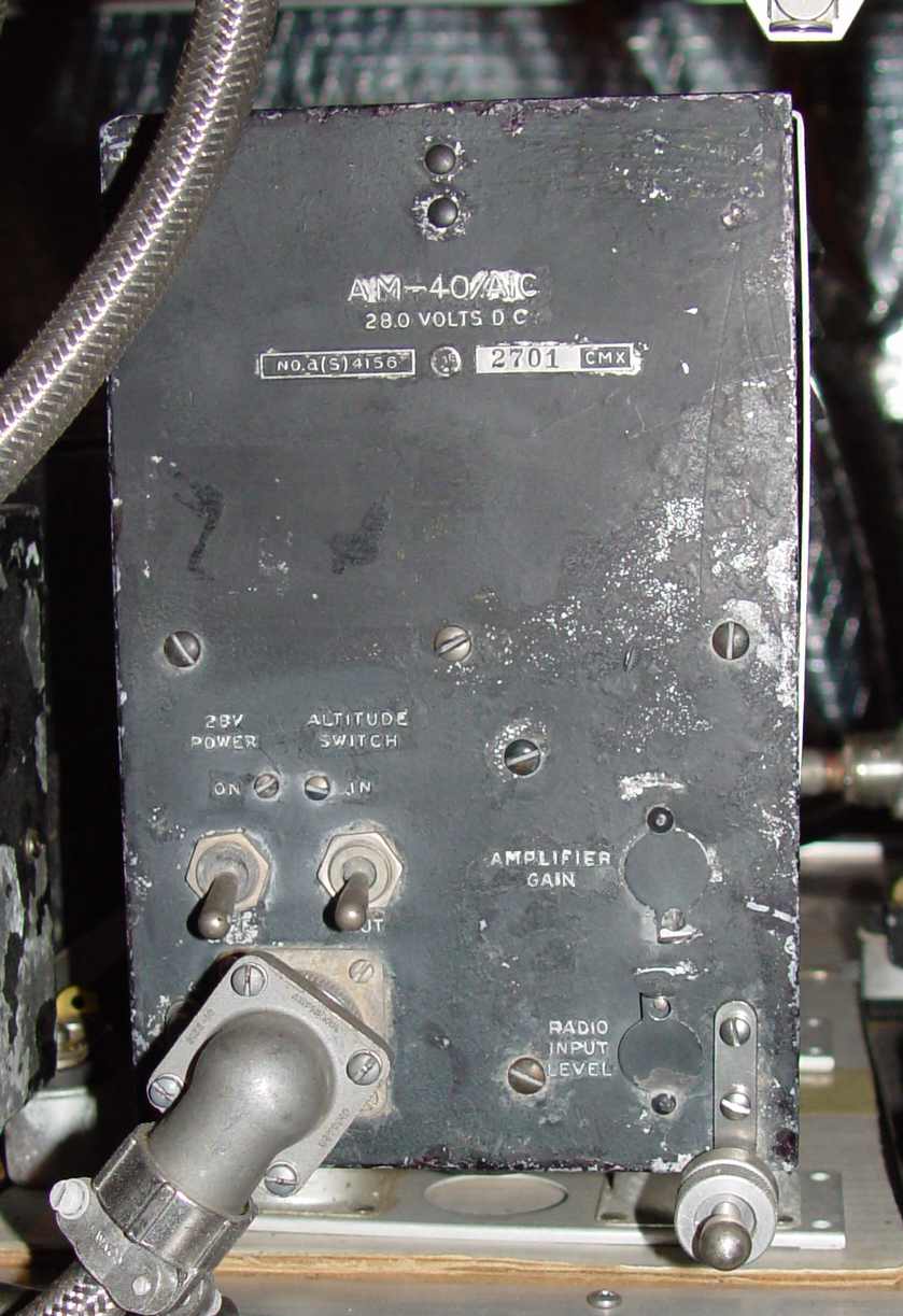 AM-40/AIC-4
The amplifier above was most often associated with the ARC-5 equipment in Navy aircraft (although the the RL-5 through -9
described above was still used to a wide degree.) This system used a single three stage pressure switch rather than the three individual switches of the earlier AIC-2.
The AIC-4 system used several station boxes, including those below:
 C-173/AIC-4 "station" control unit. This one is missing the microphone umbilical.
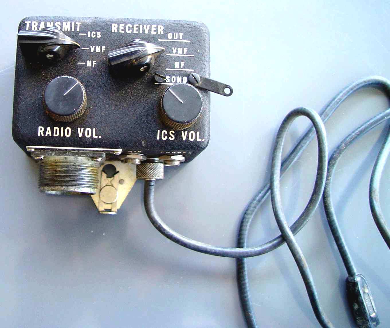 C-174/AIC-4 "operator's" control unit. Notice the added number of channels on this one, including one for the sonobuoy channel when needed.
A rotatable plate blocked it off when not in use.
C-174/AIC-4 "operator's" control unit. Notice the added number of channels on this one, including one for the sonobuoy channel when needed.
A rotatable plate blocked it off when not in use.
A schematic and associated interphone wiring is shown here.
*************************************************************************************************
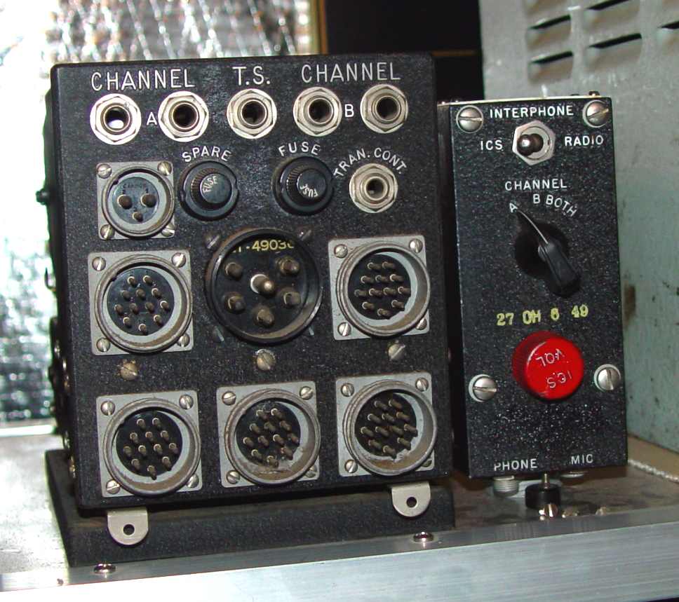
 AN/AIC-5 components: OA-53/AIC-5 amplifier on top, C-379/AIC-5 station box to the left, C-380/AIC-5 control box to the right.
The interphone system above was the last one 'type-issued' before the end of the war, and reflected the growing need
for multiple channels, especially on patrol and countermeasures ferret aircraft, both to reduce the information load
encountered using a common channel and to separate classified discussions
from the flight crew segment. It also reflects the growing complexity demanded of the flight crew to
get switches in the right position! It was powered by two separate command receiver type dynamotors on the rear deck,
either of which could supply the entire set of five independent amplifier modules contained inside the set. Master
volume for each of the five amplifiers is adjusted on the front of the set. Note the prewar five pin "auxiliary power" connector
at lower left that was fairly ubiquitous on Navy sets of all types. It provided B+ from the dynos and 28 volts DC for peripheral
devices such as frequency meters and the like.
*************************************************************************************************
 LS-184/AIC-10 aircraft loudspeaker
The operating spaces in WWII aircraft were so noisy that no loudspeaker was practical. It wasn't until several
years after the war that an "official" aircraft loudspeaker was nomenclatured - a pair of speakers that look like they
were drawn from Navy shipboard practice. The LS-131 driver, coupled with a straight trumpet; and the LS-132 folded horn, part of the AN/AIC-7. This system does not appear to have been widely installed, however. The first aircraft speaker designed and produced in any appreciable numbers was the
LS-184/AIC-10. Incorporating a small "pencil" tube amplifier that needed 175v B+ from an
external dynamotor set, it at least has the same black wrinkle finish as the WWII components,
and sounds surprisingly good. This is one of the whimsical exceptions to the equally whimsical 1939-1945 acceptance
window for the 'flight deck' in order to satisfy a special need, since my Wright 3350s are in the shop for repair
anyway (earphones are okay, but not all the time....)
Return to the "peripherals" page