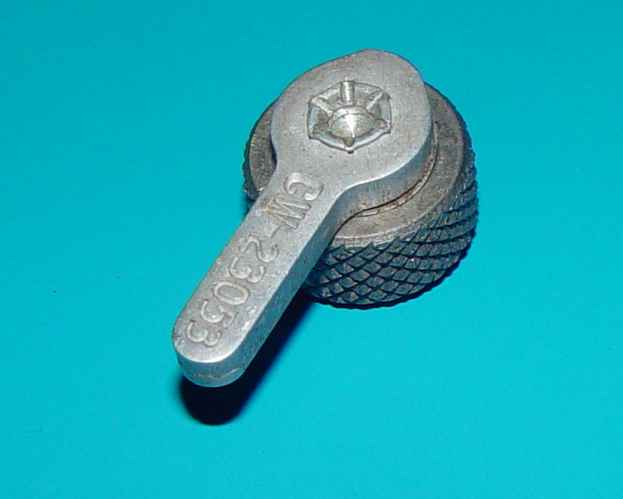
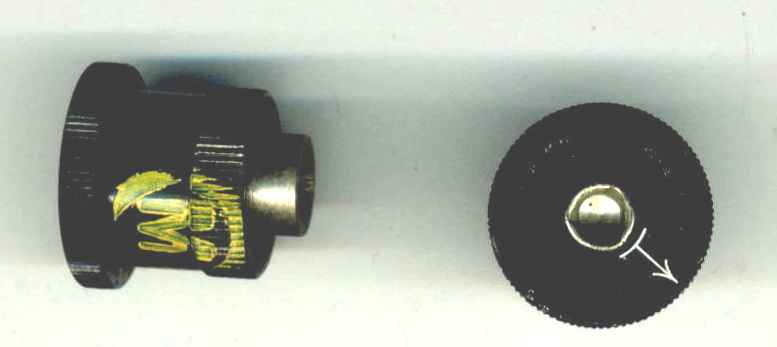
ARC Type 23053 series loop switch local control knob assembly, this one made by CW (Bell Telephone Company, whose manufacturing arm was Western Electric).
Yes, ithis page is probably longer than it needs to be, but there are several aspects to cover...
Just about everyone who has owned an R-23/ARC-5 (28v), R-148/ARC-5X (12v), or R-24/ARC-5 receiver has likely wondered why you would need the loop antenna ability, not to mention how the loop antenna switch was toggled between loop and long wire antenna. Borne of some obscure 1939 RAV Navy contract requirement that was not included in the subsequent ARA† and SCR-274N command receivers (jumping from the prewar Navy RAV to the mid-war AN/ARC-5), Aircraft Radio Corporation (ARC, not to be confused with AN/ARC)) dutifully provided the capability in two variations without a hint as to why they were included in the ARC-5 navigation sets. The 1940 RAV manual blithely mentions using either a "fuselage" or "headrest" loop that was the type that was largely in use for fixed homing DF before the war. Interrogation of the usual suspects shows examples of these loops being used on biplanes and early combat aircraft, but never being very widely fielded by the time the war began. It seems that Bendix had pretty much overtaken the loop direction finding world by that time, likely influenced by their strong interaction with military navigation engineering groups like the NRL and ARL, if not publicity with pilots like Amelia Earhart. As a result, the usual habit of using inflexible loops with general purpose comms receivers was begining to wane.
A bit of history is probably in order. You can cut to the chase below if you don't have a need to read it. Back in the early 1930s when ARC began making a name for itself, aircraft DF was already fairly well advanced from a theory standpoint. What was not yet optimized was the basic architecture of the hardware being used. At first, communications receivers were simply hooked to a loop andtenna and it permitted aircraft to "home in" on a strong beacon or broadcast station, for example. The first RU receivers made by ARC thus contained loop antenna terminals.
ARC made swapping coil sets easy to do when necessary (military frequencies were't usually in the broacast band) and it became necessary to switch the antenna between a loop and a long wire. That of course resulted in the first local loop switch knob, known in Navy circles as the CBY 23050 (CBY being the Navy code for ARC.) One more was introduced (23053) that is labeled for the dual coil local control, but they both appear identical. The September 1945 NAVSHIPS 900,109 directory shows 16 June 1934 as the initial date of entry.
The trend by the mid 1930s was toward specialized loop preselectors that were then connected to communication receivers. The tuned preselectors sometimes had built-in loops, like the DU-* series, and sometimes separate loops like the DW-* series. However, they all needed a comms receiver to detect and provide an audio output for headphones. The comms receiver was fed by a single shielded wire from the preselector, and the preselector could switch between the loop and a long wire antenna.
Those communication receivers had already sprouted twin "loop" antenna terminals earlier, but the inertia of progress probably retained should the need arise due to a failure of the specialized loops, and for the situations where there was no one to operate the preselector loops.On the 1940 RAV Type CBY 46102 and CBY 46103 receivers, there was a more elegant local switch knob provided as a part of the contract. For the AN/ARC-5 nav receivers, they simply resurrected it - with the same ARC part number - 7491. Here is where it gets interesting - the 7491 is mentioned in the NAVSHIPS 900,109 Directory only in the A/N subdirectory as an ARC-5 component. A close examination of the knob assembly shows a close match to the construction of the Local Tuning Control 6743! That is perhaps not surprising, as the loop switch knob interfaces the same mounting thread and male spline also seen on the right side of the receiver that is connected to the tuning capacitor.
† Where it gets more curious is a modification to a subset contract for the production of two different ARA receivers, called out as CBY 46129(modified) and CBY 46145(modified), designed to work with the Model ZA blind landing equipment. It would be reasonable to assume that ARC used the same parts as the RAV navigation receivers. But no...in the parts list, they specify two controls for the receivers - one local and the other remote. The part number for the local loop control is not 7491, but rather CBY 23050! The RAV set did not offer a remote loop switch, but for the modified ARA nav receivers, the part number was given as CBY-23051! The reason that is puzzling is that the Navy part-numbered controls have a male square drive output, and the RAV antenna switch needs a command set female spline input of the 7491. More on that below the ornge line.
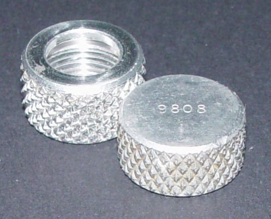
Before that though, we should briefly mention the closure cap if you don't have one on the receiver. They are simply a standard flex cable nut without the hole, shortened to 5/16" in height, shown below.
Back to the two ARC-5 loop switch controls, the first is arguably the easiest to fabricate.
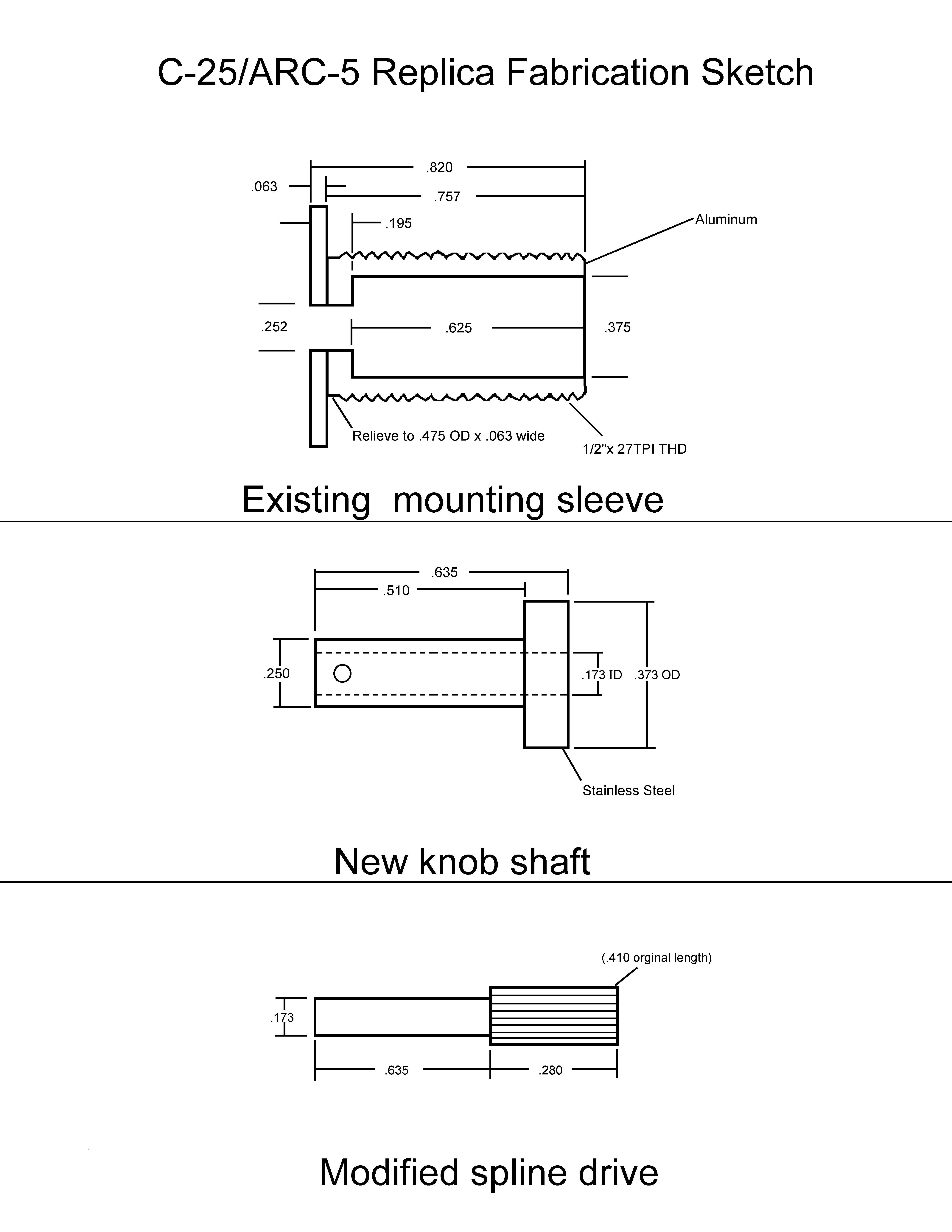
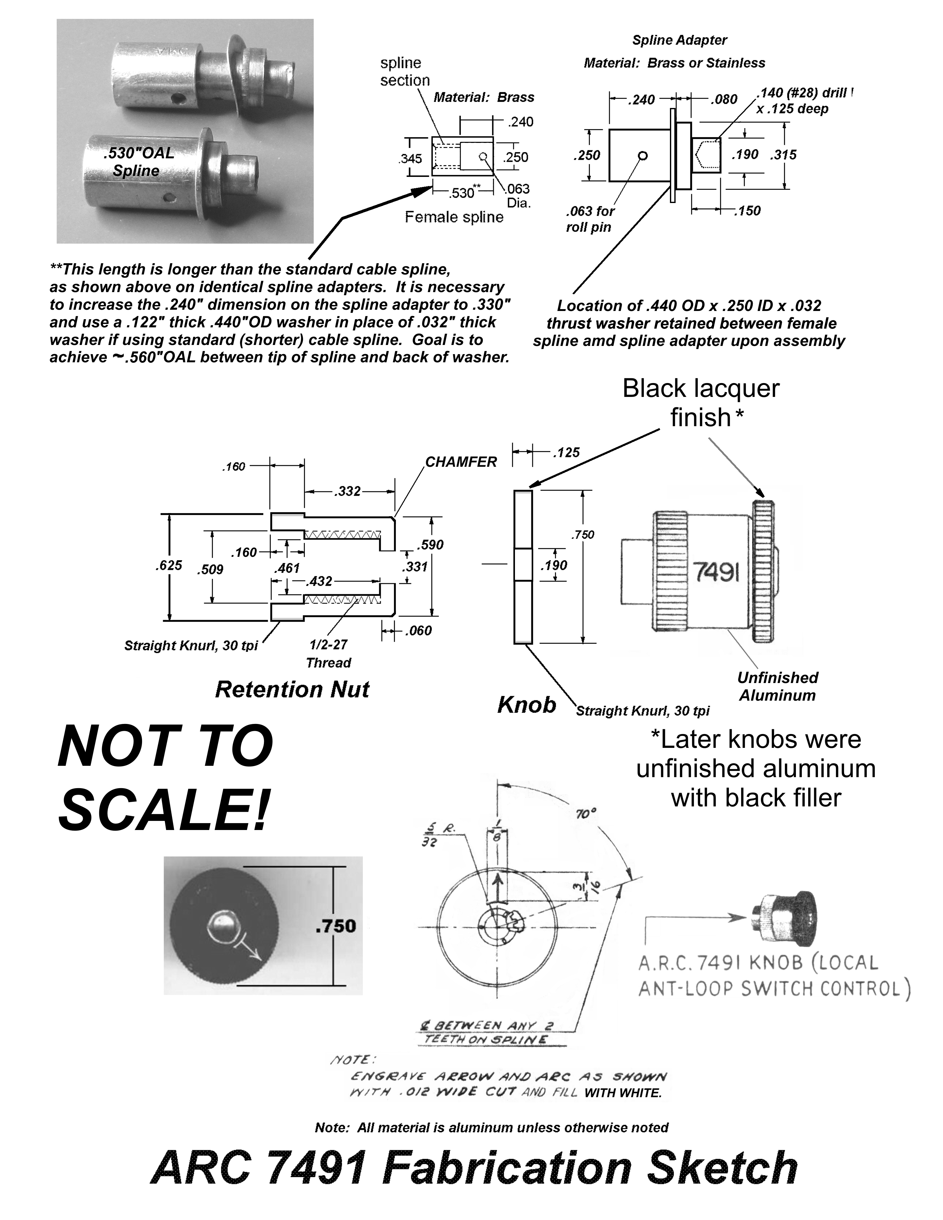
Below is a fabrication sketch that might be useful if one wishes to replicate the 7491 switch knob assembly.
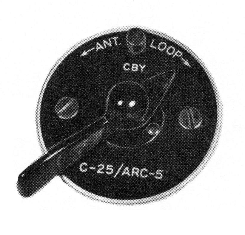
So, there was one significant difference between the RAV and the AN/ARC-5, and that was a prolific use of remote control accessories in the latter. What to do for this loop switch for remote use? Rarely spending time on designing anything when something already existed, the ARC engineering eye fell back on one of remote controls for the 1930s RU series of receivers they had manufactured, and voila! The obvious solution was in the form of a repurposed CBY 23052/23054 remote loop antenna switch control, renomenclatured as C-25/ARC-5.
It is tempting to think that it would be easy to modify one of the older remote controls, especially if all it entailed was installing a different 2" diameter disk painted satin black, with a little appropriate engraving on it. Like everything though, the devil is in the details. As mentioned before, the 1930s controls were designed to use a 1/4" square male drive head on each end of a .335"OD" flex drive cable. The ARC-5 equipment used smaller female spline drives on each end of the same drive cable (yay!). What this means is that either: 1), you have to put a 1/4" male square drive tip on the control end of the cable, or 2), install a male spline (like the one you see in the end of the loop switch cover) inside the control to replace the female square drive end. The latter is what ARC decided to do.
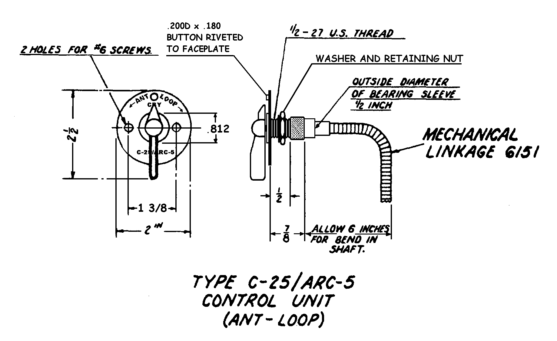
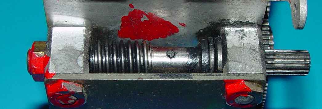
One thing that complicated things was bearing support for the male spline in the control. The female square drive end in the original design had a "built-in" bearing in the form of the threaded mounting sleeve, as you can see below:
Wobbling around without a robust connection to the threaded knob mounting sleeve, the male spline has no such support, so they decided to provide a 1/2" x 3/8" diameter "bearing" surface on the back side of the cable nut to help stabilize the assembly. On the receiver end, the switch bearings stabilize the male spline, so that's not a problem. Sadly, they didn't provide any drawing to show how this bearing was made, or where it fit in the end of cable stack. It's not clear why this wasn't described in any of the manuals, but by the time of publication, it may have been that few units had intentions of installing the C-25 control, making any detailed mod of the end of the fexible shaft a subject of a separate document when and if needed. The approach below is simply my guess as to one way it can be done. It seems to work fine and doesn't require making a special end for the normal ARC 6151 flex drive cable. It does, however, require either boring out the square drive end of the control shaft to .347"ID, or making a new shaft with the same dimensions shown.
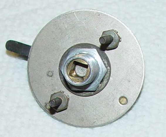
Getting back to the idea of dismantling one of the earlier RU or MC-135 controls, it isn't a subject for the squeamish. Here are the steps necessary:
1. Remove the knob. This is not as easy as it might appear. The problem here is that the pin through the knob is one of the three groove dowel pins that deform the hole as they are installed, and once installed they resist removal like they were part of a weldment. They are mercifully not hardened, at least. The only way I have ever been able to get them out cleanly is by carefully spotting the head on each side with a 1/32" spotting or center drill, and drilling .130" depth from each side with a 1/16" drill. You'll need some serious magnification help to center the spots. The reason for drilling it from each side is that the slender drill bit likes to wander on a long 7/16" hole, so you want to keep the depth as short as possible.
2. Wedge the the knob off with two large flat bladed screwdrivers tapped in with a small dead blow hammer. That leaves a small section of the pin through the center of the knob shaft, and you can drive that out with a 1/16" pin punch. I recommend throwing that pin remnant as far as you can into the forest, as it has some bad juju... You will be replacing it with a 7/16" slotted spring pin that is easily installed and easily removable.
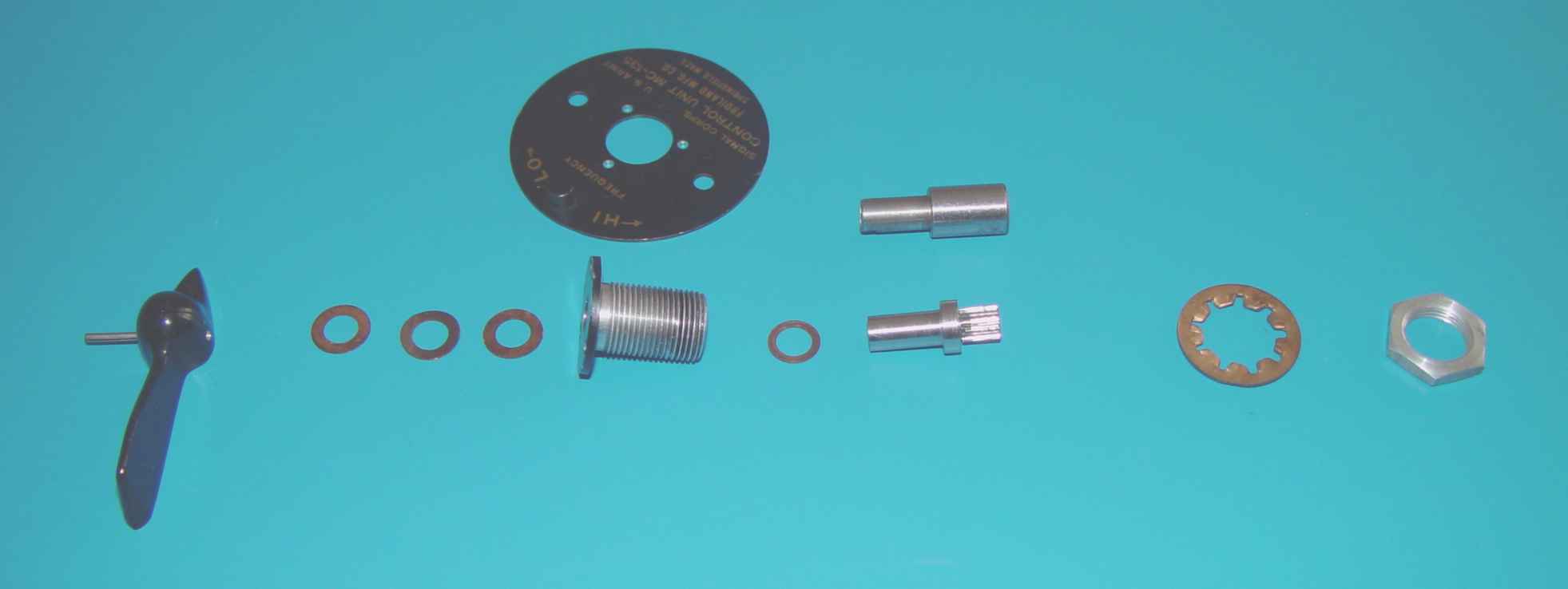
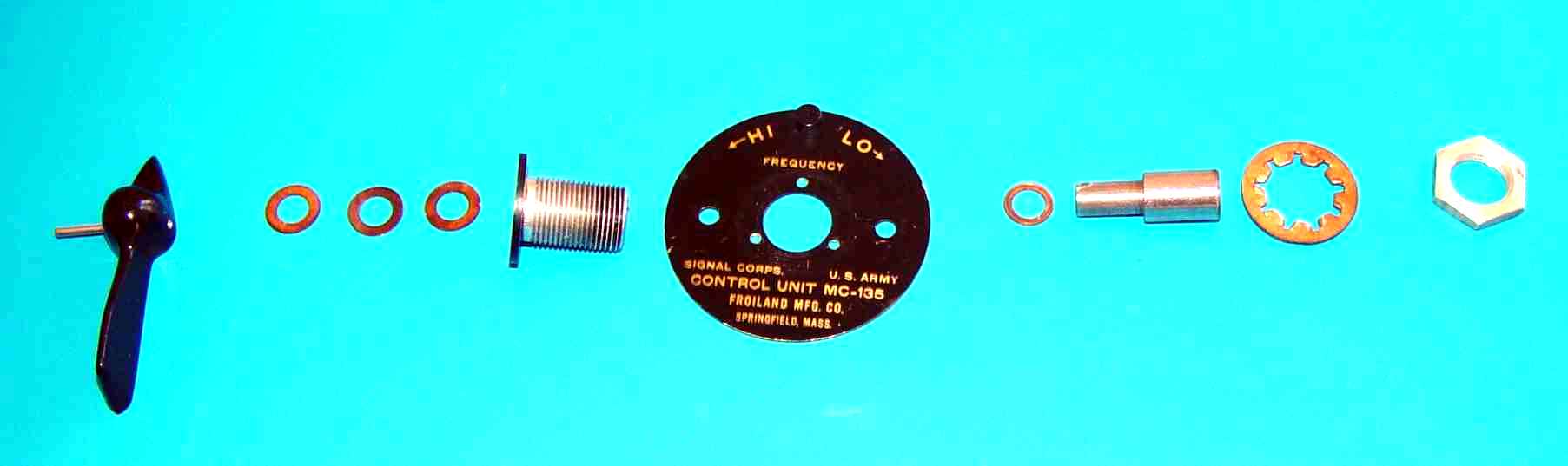
3. Remove the three phophorus bronze wave washers from the shaft, and it should then slide out of the threaded bearing assembly towards the rear. That will reveal the knob shaft and bearing. See exploded view below.
If you've gotten this far, you may be wondering why you ever began, but the hard part is done. You ought to be looking around for a junked command receiver, from whose #4601 main tuning capacitor you can extract a male spline from its worm gear mounting cage. And, (wait for it), it is pinned into the worm gear shaft with another accursed grooved dowel pin. The example below suffered from a heavy object hitting the capacitor blades, so it was appropriate for harvest.
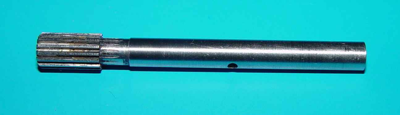
So with the shaft out of there, you have a couple of alternatives to consider. I'll just cover the one I chose below, but whatever works for you best.
With the spline shaft out, I cut the shaft to the dimension shown below, along with making a new 1/4" diameter knob shaft. I made the two so they were a mild press fit, though it isn't critical.