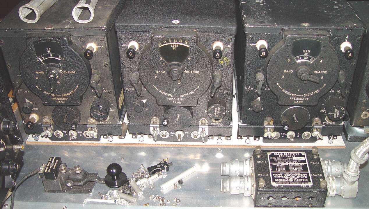
Of all the military Services, the Navy was the most interested in airborne signals intelligence prior to the beginning of the war. Installed on many of their patrol aircraft, the General Electric RAX-1 trio provided a continuous search capability from 200kHz to 27 MHz, as well as doubling as a fine liaison receiver capability. Shown here, with one of my typically spotlessly organized ad hoc workbenches, is the entire set, including the three shock mounted racks, as well as the junction box that is used for both power and earphone connections. Schematics for the three receivers are located here.
This receiver had a number of unique characteristics, including excellent stability and performance. For example, it used fairly conventional circuits but plate voltages that were 2/3 of those in most other designs. The dynamotor on the rear of the receiver provides 166vdc, lowering noise and extending tube life. A single antenna could be daisy-chained through all three receivers, and was carefully isolated by filters to avoid local oscillator interference between receivers. For unknown reasons, this 1940 GE RAX design followed the ARC's circa 1934 Type K in using the concept of plug-in shelf racks for the receivers. (See The Original "Command Set" for more on the Type K.) The approach may have been driven by a Navy design specification, but I haven't yet located any documentation on it. In any case, the RAX had a more complex execution of the idea than the ARC design - it required special aluminum castings in both the receiver and rack, adding unnecessary weight and expense to the design, but was none the less an elegant engineering solution.
The built-in tube puller for each receiver (two are on top of the left receiver) was a wonderful idea, but is useful only for the metal receiving tubes of the type in this set. The circular end is slipped down over the tube and the paddle handles squeezed to grip the tube and wiggle it out. It is relatively easy to develop significant pressures, so using it with a glass tube is a chancy operation. ARC (Aircraft Radio Corporation) offered a servicing kit for the famous command receivers that had an almost identical puller, but being a part of the expensive "five meter" test sets, it wasn't attached to every receiver, and was therefore one of those tools that was hoarded by every technician lucky enough to receive one.
The shock mount "chairs" under the racks have convenient handles for releasing the snapslides, but with 12 of these little top-hats to mount after drilling the 48 holes necessary for three receivers, and still expect them all to line up properly, the only practical way to do it is using a couple of aluminum "C" channels to mount all the feet on, and then mounting the two channels in the aircraft (or in your radio shack). The original RAX rack mentioned below (Serial numbers 1-75) simplified that process for the installer, leaving just four chairs to install on the four corners. Apparently there was enough operational demand for installation of only one or two receivers to eliminate the wide rack from the acquisition chain.
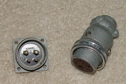
Another of the more frustrating collection challenges has been the search for the uncommon connectors.
The RAX uses a 4 pin "coarse thread" Cannon connector that I've seen on no other piece of WWII
equipment, shown above. To compound the problem, the entire set (with junction box) requires seven of them!
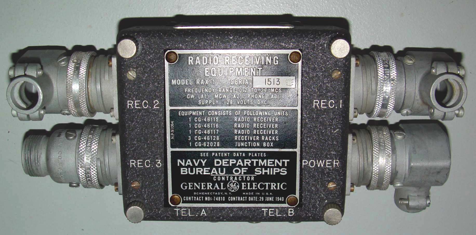
The one part of this set that is perhaps the most difficult to find is the junction box, CG-62028. For some reason they have been drawn to the innards of the
galactic black hole. Below is what one of these little jobs looks like. There is a set of four phone jacks along the bottom edge for troubleshooting or extra
audio feeds to equipment, like interphone systems.
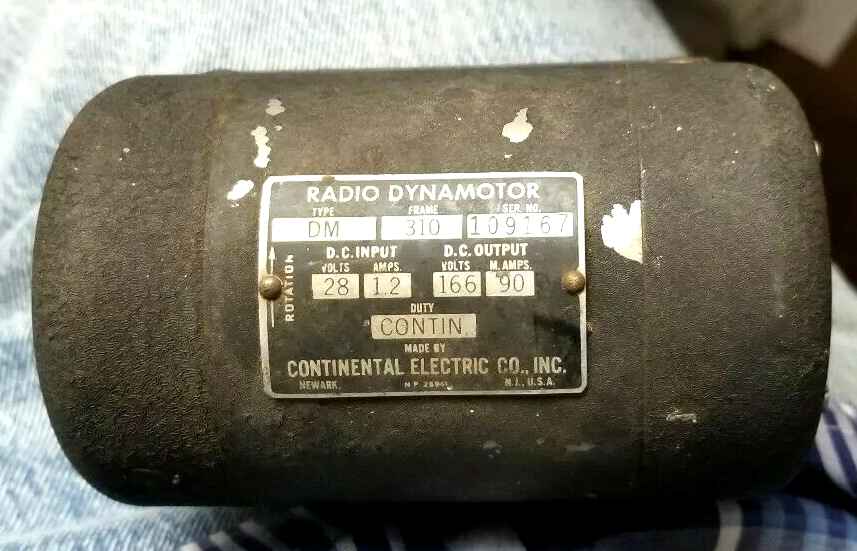
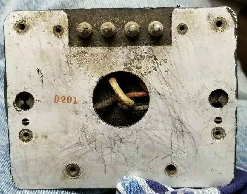
The dynamotor pictured below is also unque, unfortunately. It has an identical frame size to the command set dynamotors, but besides its unusually low voltage, the mounting plate has four of the medium size banana pins in a line, along with a nice feature - it only takes two knobs to unclip the dyno from the receiver, and the handles for accomplishing that are easy to grasp, unlike the four used for the command sets, for example. It uses the same handles as the shock mount chairs under the racks.
This set originally began in a 1940 contract in a slightly different form. The initial manual for the equipment covers only receivers with serial numbers 1 to 75, and displays the single rack for all three receivers, shown here.
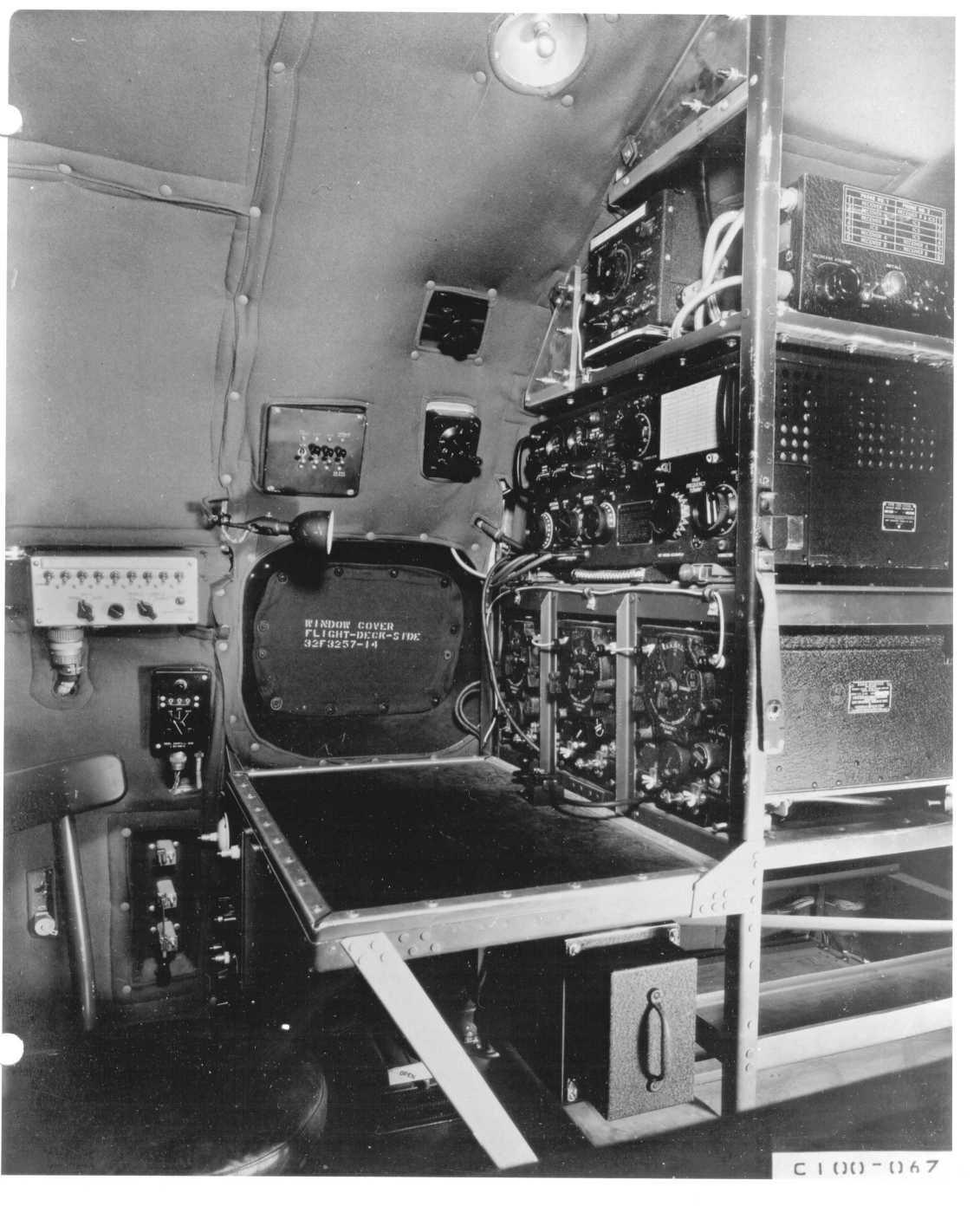
Below is a photo of the triplets installed below an ATC/ART-13 in a Navy PB4Y2. Note the two Plexiglas antenna patch panels above the equipment. These are equipped with "spark plug top" male connectors, and patch cords made with "Rajah" spark plug spring connectors are employed to select the antennas being used for receive and transmit. You can also see these on the top of the GO-9 at the bottom of the page here.