Bendix Radio enjoyed a very close association with the Navy as early as the mid-1930s. Some of their equipment, like the DU series loop preselector for the RU receiver and their MT-11B telegraph key, was even redesignated with Navy numbers and used throughout the war. By the time the war came, the light gray wrinkle finished commercial aircraft gear was being specified as standard equipment for several Navy aircraft, without the usual re-nomenclaturing ceremony. The Signal Corps eventually adopted the MN-26 DF receiver for many of the USAAF aircraft as well, and of course the SCR-269 and its antecedents, and the AN/ARN-7 culmination of that line were also Bendix products.
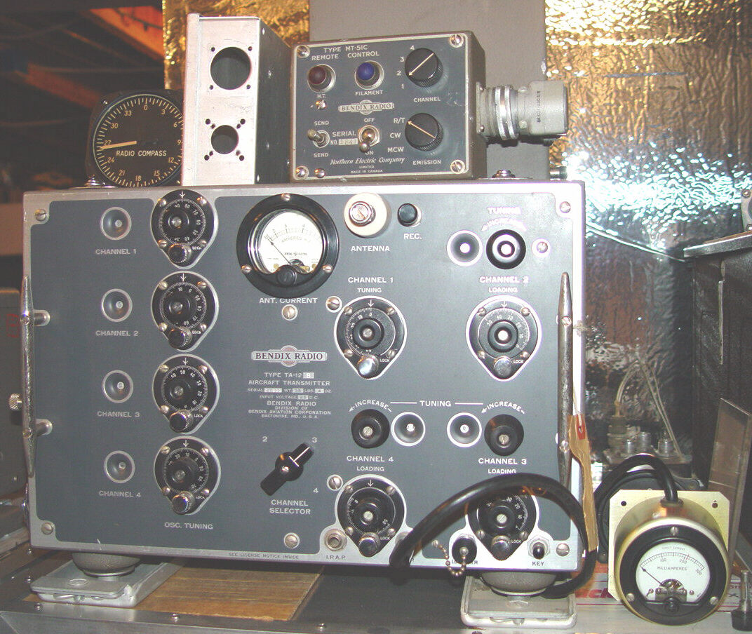
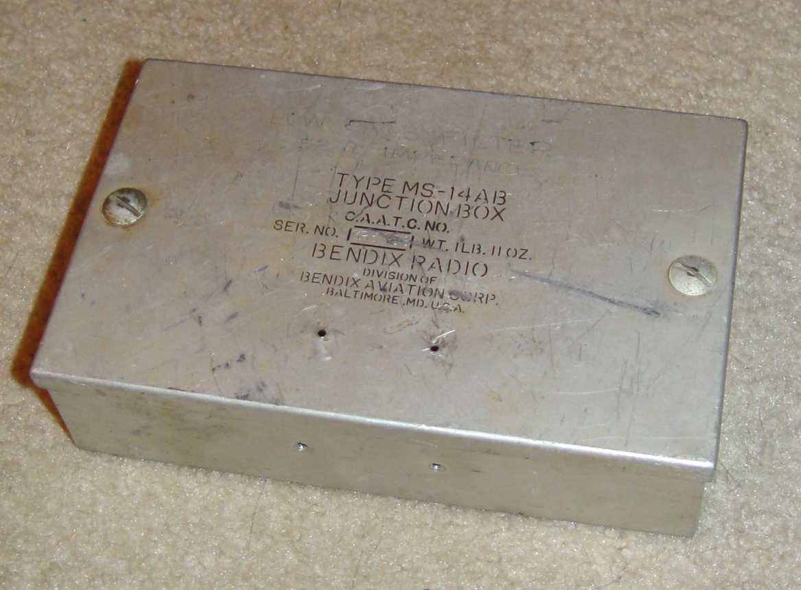
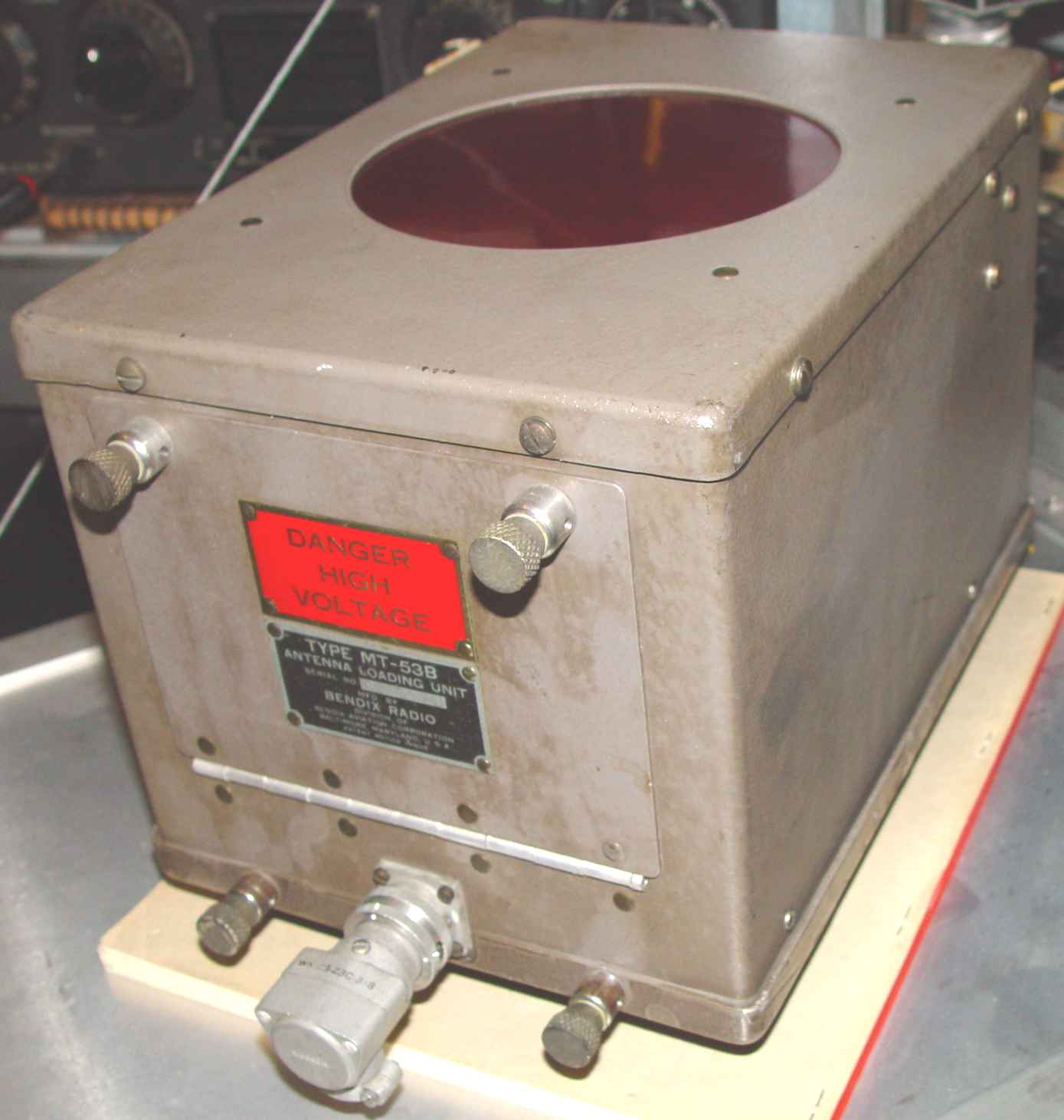
The example below is the TA-12B model, which differs from the more common -C model only by the frequency range. It was primarily used for shorter range HF comms in light aircraft. It is shown with its MT-51C control box, MT-31C tuning meter, MS-14AB junction box, and MT-66A dummy load (partially seen at top right. The dummy load is adjusted to simulate the trailing wire antenna of whatever aircraft is being used at the time. (The radio compass is just perched there for scale.) Unseen behind the transmitter is its MP-28BA dynamotor/modulator, and an MT-53B MF antenna tuning coil. I need to add another layer to the rack, obviously...
The mating receiver used by the Navy for this transmitter is normally a Bendix RA-10, but that is detailed over on the Navigation page, as it was also used as a DF receiver.
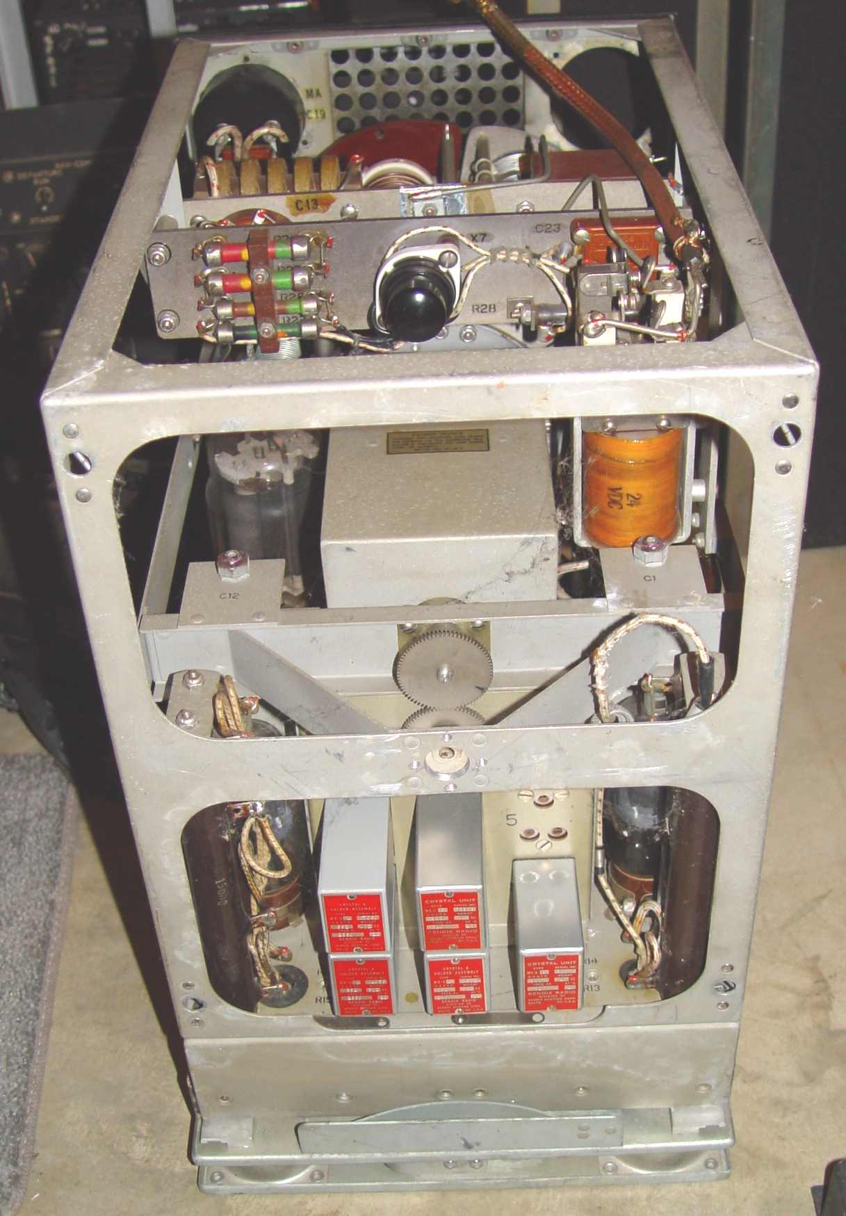
***********************************************************************************************************************************************Probably because of commercial aircraft lineage, a late 1930s Bendix transmitter was used in some Navy transport aircraft as another high power alternative to the Navy GO series, (see Navy Day) despite the continued production of the Westinghouse GO (-9 by then). The TA-2J under restoration below was a significant improvement over the GO-* series in that it was capable of eight remotely selected crystal controlled channels and was significantly smaller and lighter, despite using the same 803 PA. Channel selection was accomplished with a large motor driven rotating drum, containing all the tuning elements except the crystals. No tank capacitor was used, the designers having reached the logical conclusion that aircraft antennas provide enough capacitance to serve that function except for low frequency work. Schematics and system diagram are shown at TA-2J Schematics.
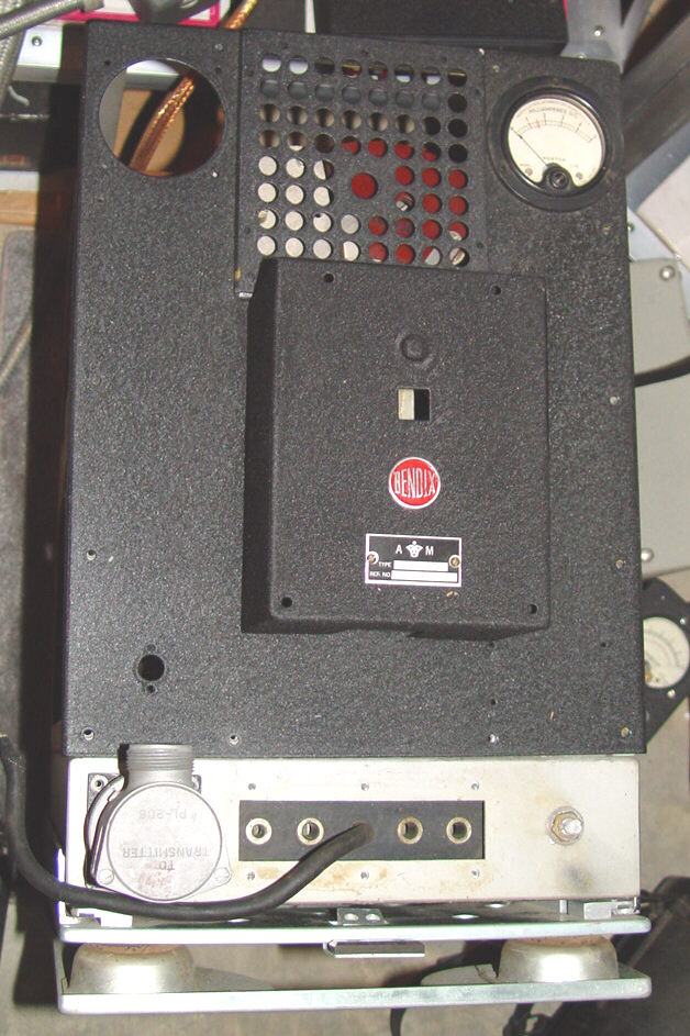
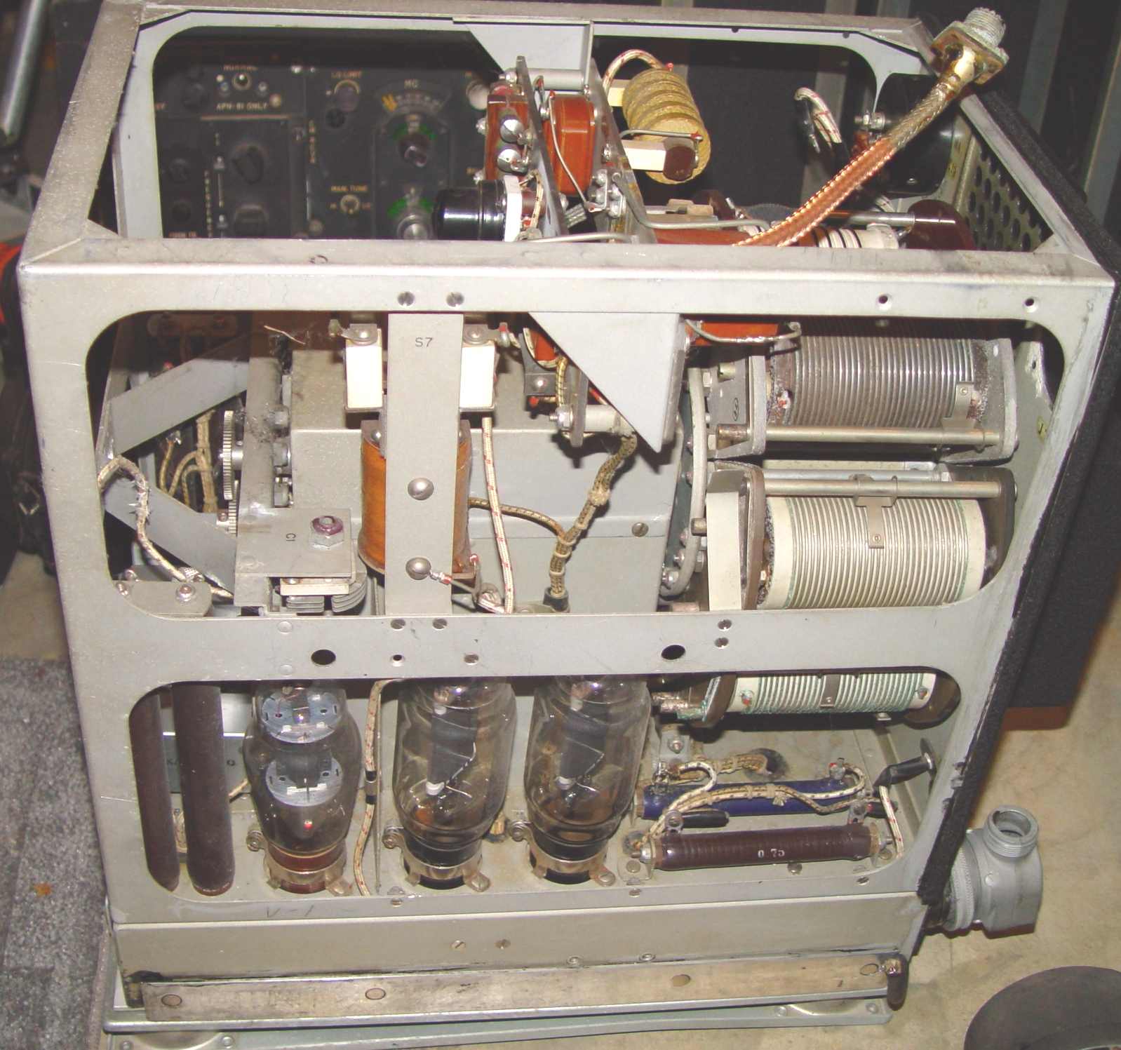
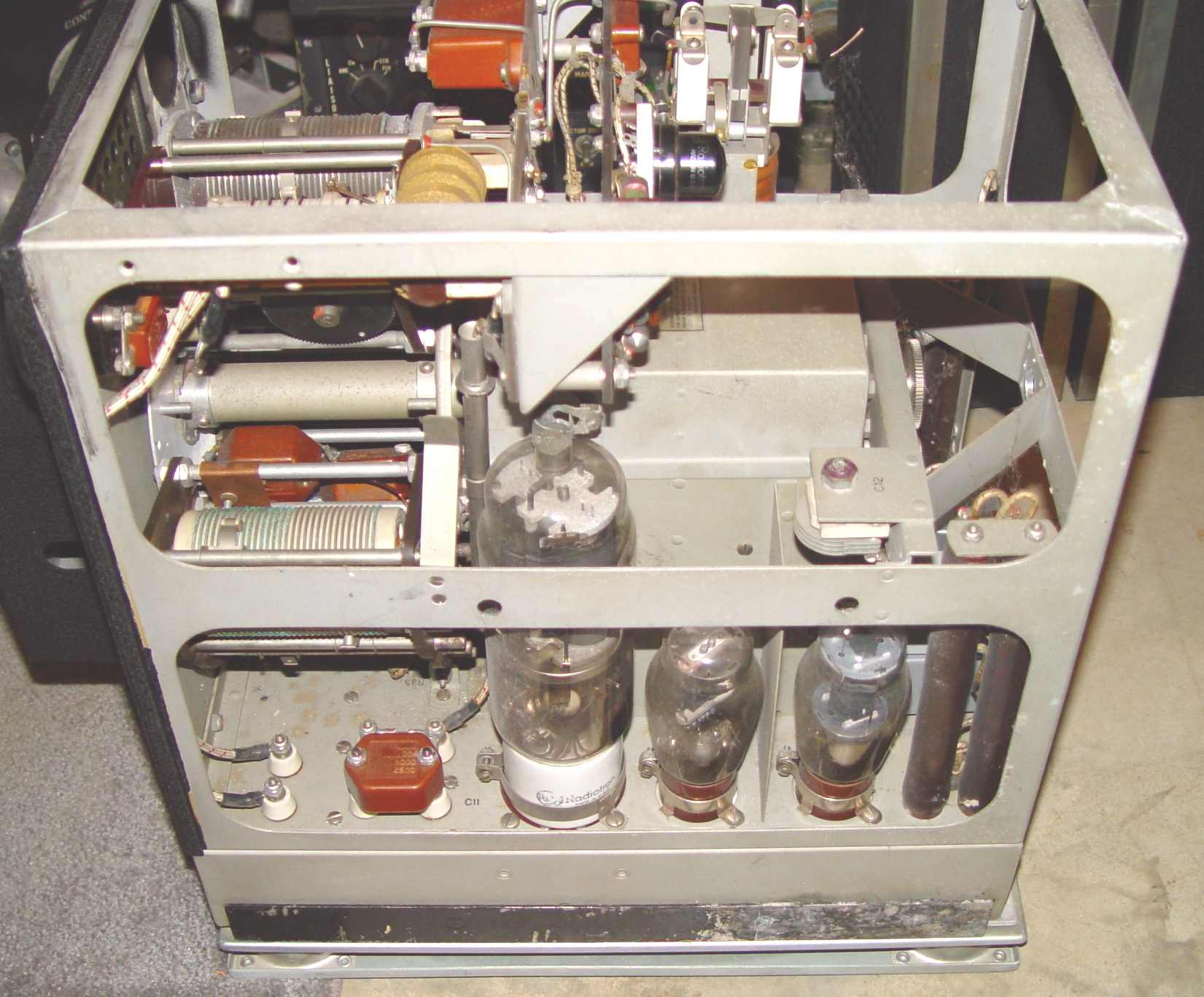
As you can see, there is really no capability for local control of the set. An emergency crank handle for changing frequencies is to the right of the doghouse "autotune" motor box, but it isn't what you would call user friendly - what seems like a thousand turns gets you to the next channel. Unlike the GO series, which was CW only, this transmitter has a built-in modulator. The antenna output terminal is installed in a Micalex plate in the hole at upper left, using a 1/4 turn Dzus fastener. This particular transmitter had the output connector converted with shielded coax and an SO-239, probably by a ham radio operator, and will be restored to the original configuration. Below are some additional views of the set interior.
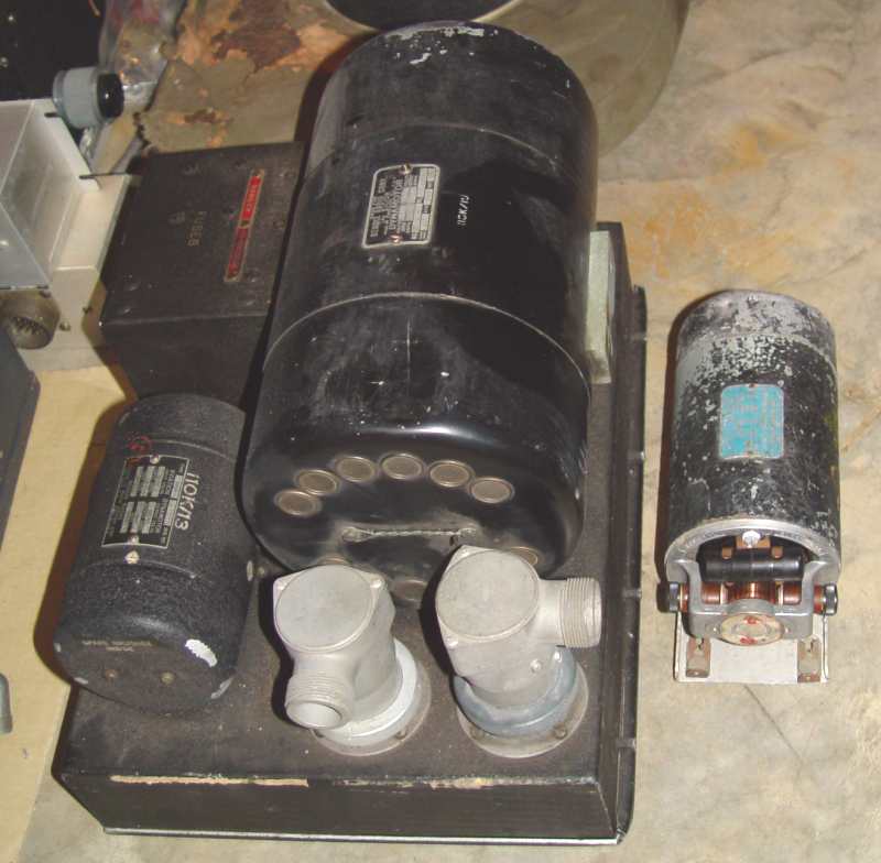
As usual with aircraft sets, there was a separate MF tuner that could be used when necessary - the MT-36 series, a box that was almost as large as the transmitter itself. The one below is a C model. Like the main transmitter, this one could be switched remotely with the MT-34 control box below it, coordinated using presets with the transmitter channels selected.
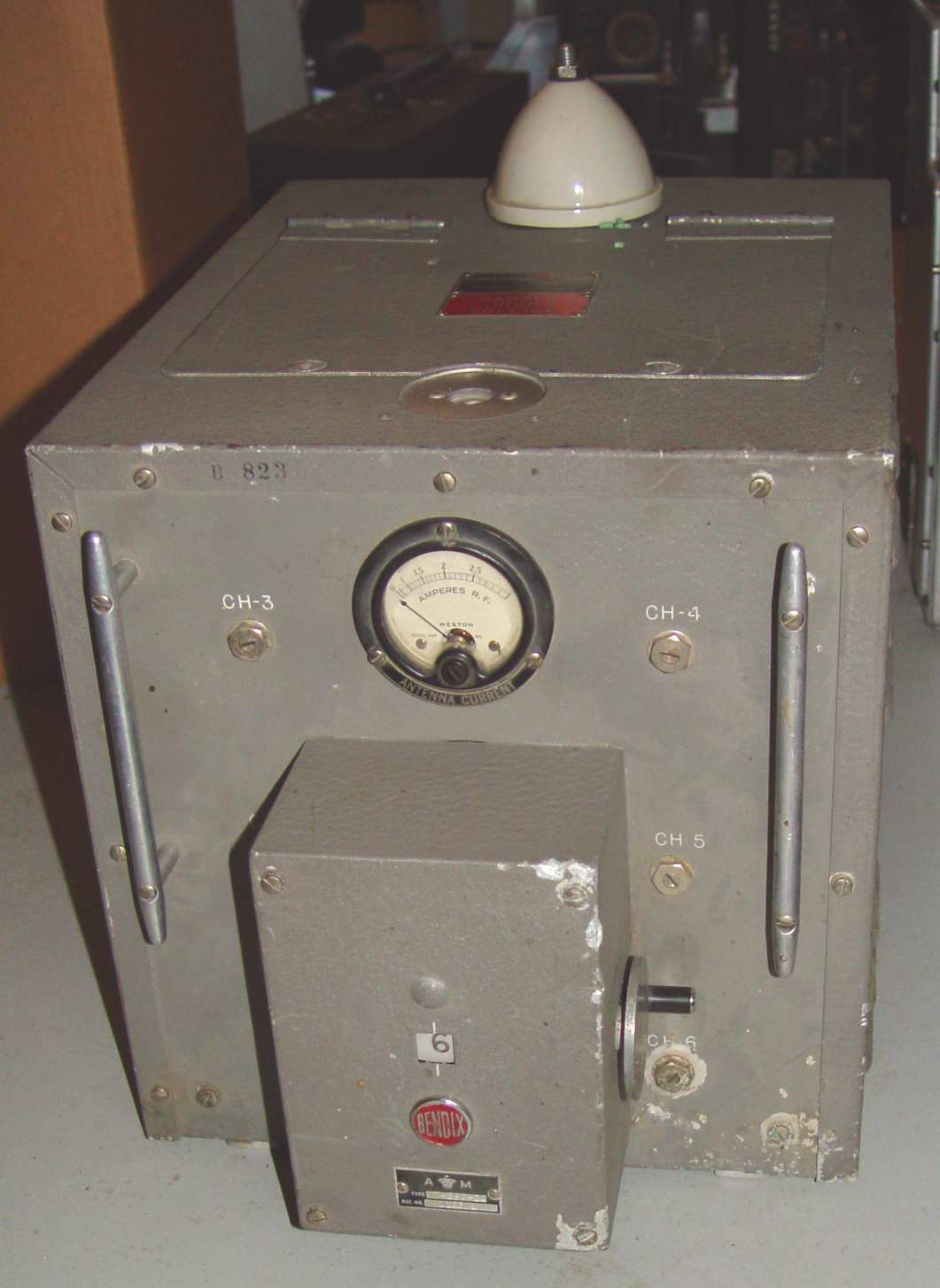


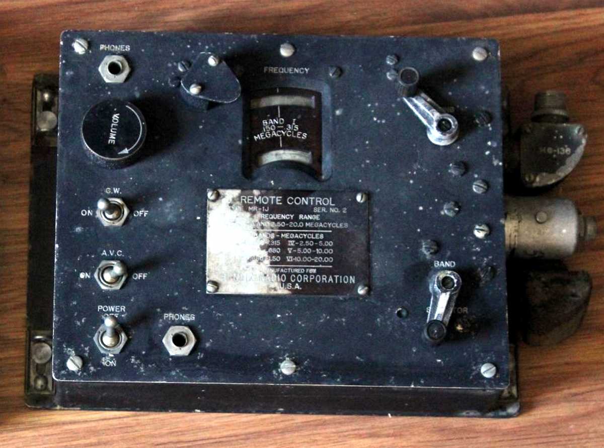
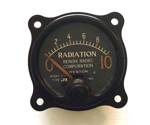
Finally, I picked up this odd little item below from a hamfest table as a curiosity, not knowing at the time what set it supported. Recently I discovered it was a part of the TA-2J series as an optional component. I was vaguely thinking nuclear radioactivity at the time I first saw it, but of course it is simply an arbitrary 0-10 scale for antenna voltage picked off by a resistance divider and rectified by a 6H6 duodiode in the transmitter. It actually only provides an uncalibrated indication of RF voltage presence on the RF output connector, not antenna current like the Bendix MT-33 remote antenna current meter does. The transmitter selector switch must be in the DIODE position to connect the transmitter to the remote radiation meter. Alternatively, one can plug the built-in meter on the transmitter panel into the GRID jack on the lower middle part of the transmitter and use the DIODE switch position to make the same measurement. Plugging in the transmitter panel meter temporarily disconnects the remote meter (if used). The MT-36 also has an RF output meter on its front panel, but paradoxically it is an RF current meter - not voltage like the other two! Why Bendix introduced this particular type of remote indicator is lost in the mists of time, but it may have derived from contract specifications by the British..."radiation" seems more like a Commonwealth term than U.S. military practice, which tends to be more like "RF Output", or some variation. I suppose sometimes it's good to know there is at least RF power being fed to the antenna, but a simple voltage indication wasn't a very common feature in aircraft transmitters.
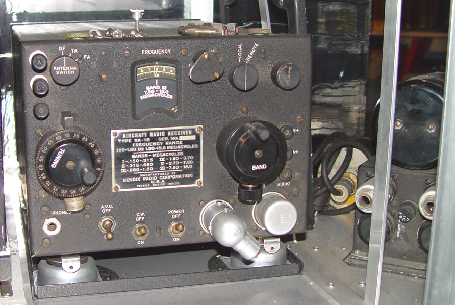
The receiver most often listed as the mate to the TA-2J in the Navy aircraft compliment tables was the RA-1B above. Possibly the only continuous general coverage receiver Bendix made until well after the war, it was compact and very popular with commercial airlines. (Their other wartime receivers all had spotty band coverage for specific purposes.) I noticed one at the Dayton hamfest a few years ago with a United Airlines tag on it. This particular unit shows the matching dynamotor to its right. Like a number of the local control Bendix sets designed in the 1930's (the original manual is dated 1938), a toggle switch in the "down" position was considered "on". This rather interesting convention reflected the British human factors influence on the design concept. The strange structure to the right of the tuning dial is a dial light. The schematic and other information is shown at RA-1B Manual Excerpts