SCR-AE-183
The 1930's bay wouldn't be complete without some representation of the lower power "command" sets - as opposed to the
greater capability BC-224-A and BC-AA-191 "liaison" set described on another page. In the USAAC, that role was served by the SCR-**-183, dating back
to the early 1930s. Some examples of the piece parts going into that set are shown below, this one an "AE" variation from 1935.
ARC designed and produced a similar set for the US Navy (called the RU/GF series), but it had some diverging differences in circuit
design and tube types as the years rolled on. I have almost everything I need on this set except an -AA- through -AF- receiver, and would deeply appreciate
any leads to finding one of those. In the meantime a nice BC-AN-229 will stand in for the real receiver.
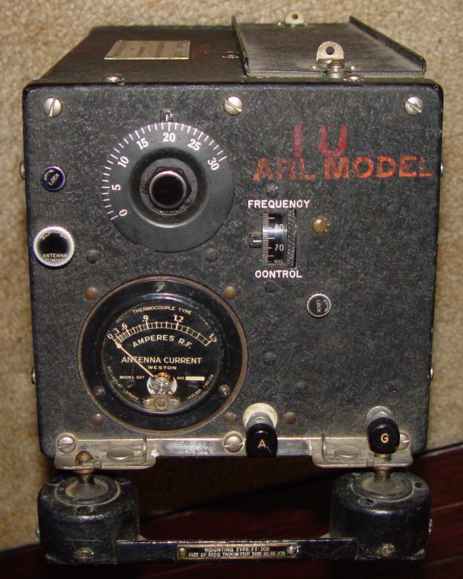
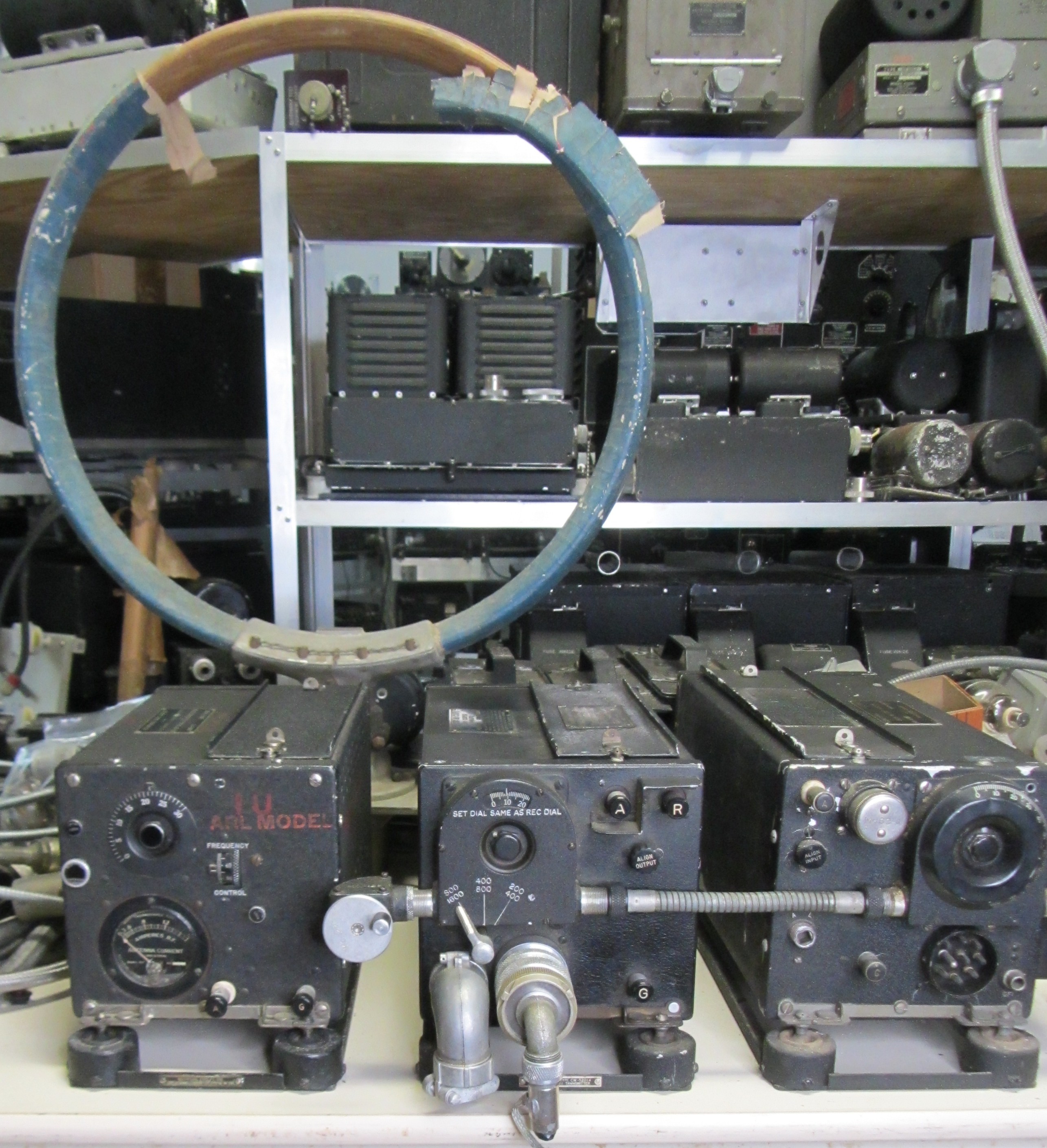
BC-AE-230 radio transmitter. "IU" signifies an "Installation Unit" intended for test fitting in various aircraft.for maintenance
clearance, ease of operation, structural support, etc.
ARL stands for the Signal Corps Aircraft Radio Laboratory, the primary aircraft radio communication
engineering facility for the USAAC from the end of WWI
through October 1944, located at Wright Field in Dayton, Ohio. Strangely enough,
the Aircraft Radio Corporation always installed black faced RF ammeters in their transmitters
starting with the first -AA- model. Western Electric also produced
three in the early series, in which they inexplicably installed the only white faced meters in the entire SCR-183 series of -AA- to -AS-.
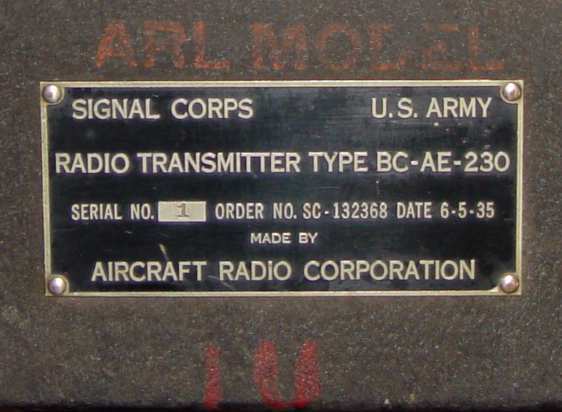
BC-AE-230 radio transmitter tag
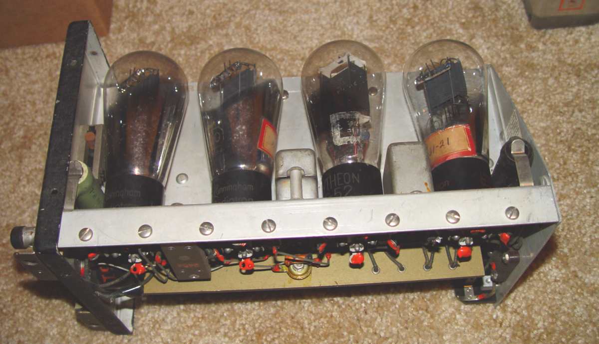
BC-AE-230 radio transmitter side view. One of the globe VT-52 PA tubes is missing, so a VT-25 is temporarily serving as a
stand-in until I can locate the correct one. Note the old paper tags on the envelopes with mu measurements recorded on them.
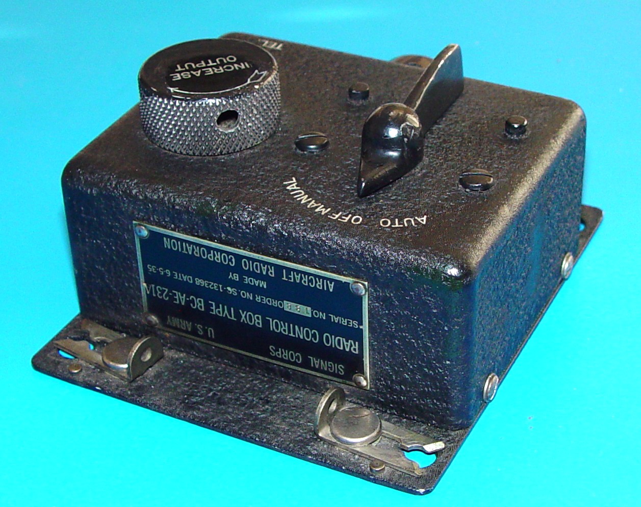
BC-AE-231 receiver control box.
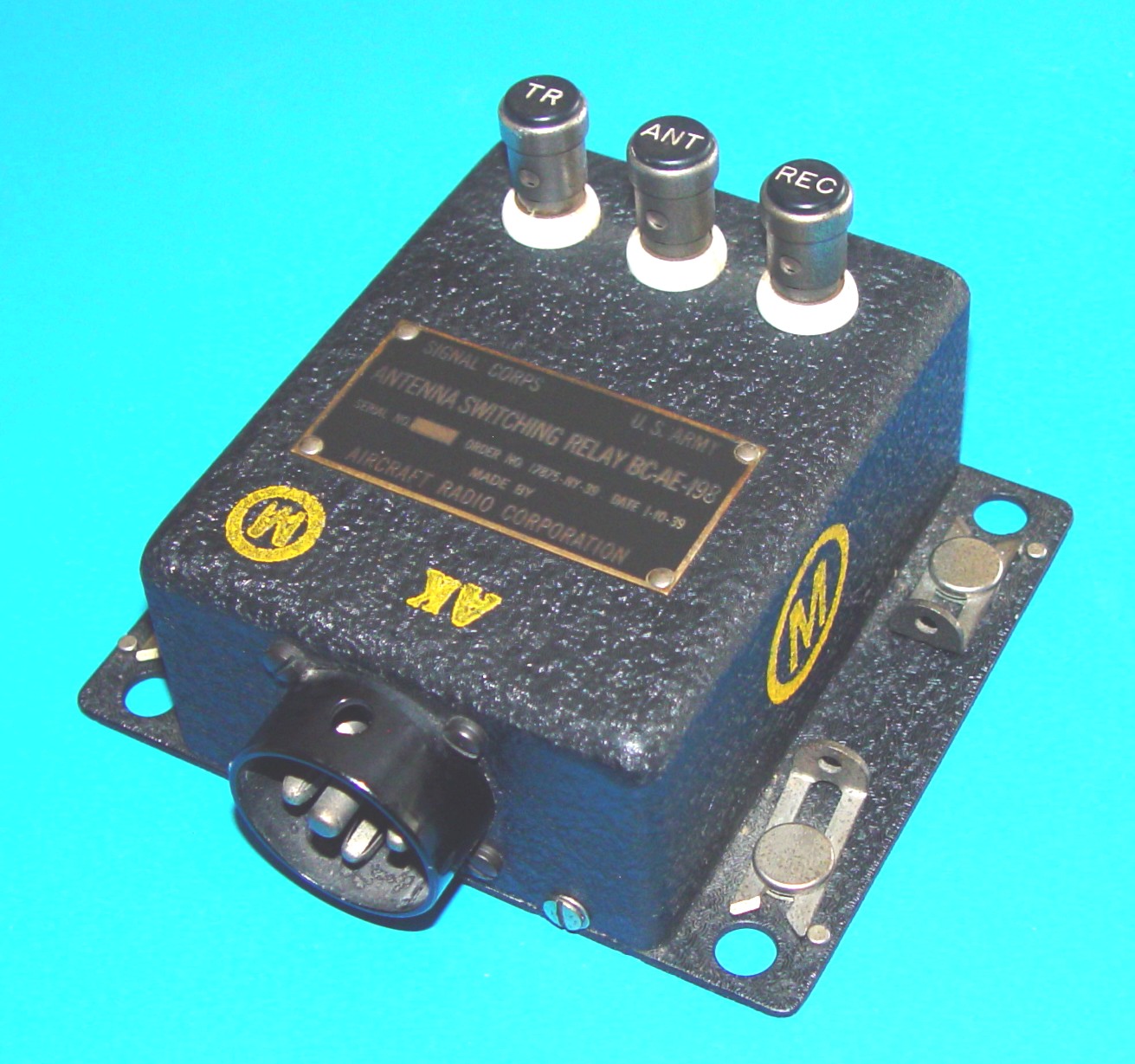
BC-AE-198 antenna relay. This one is from the ARC Morgue and has an additional curious stamp of "AK" while the metal nomenclature tag clearly says "AE".
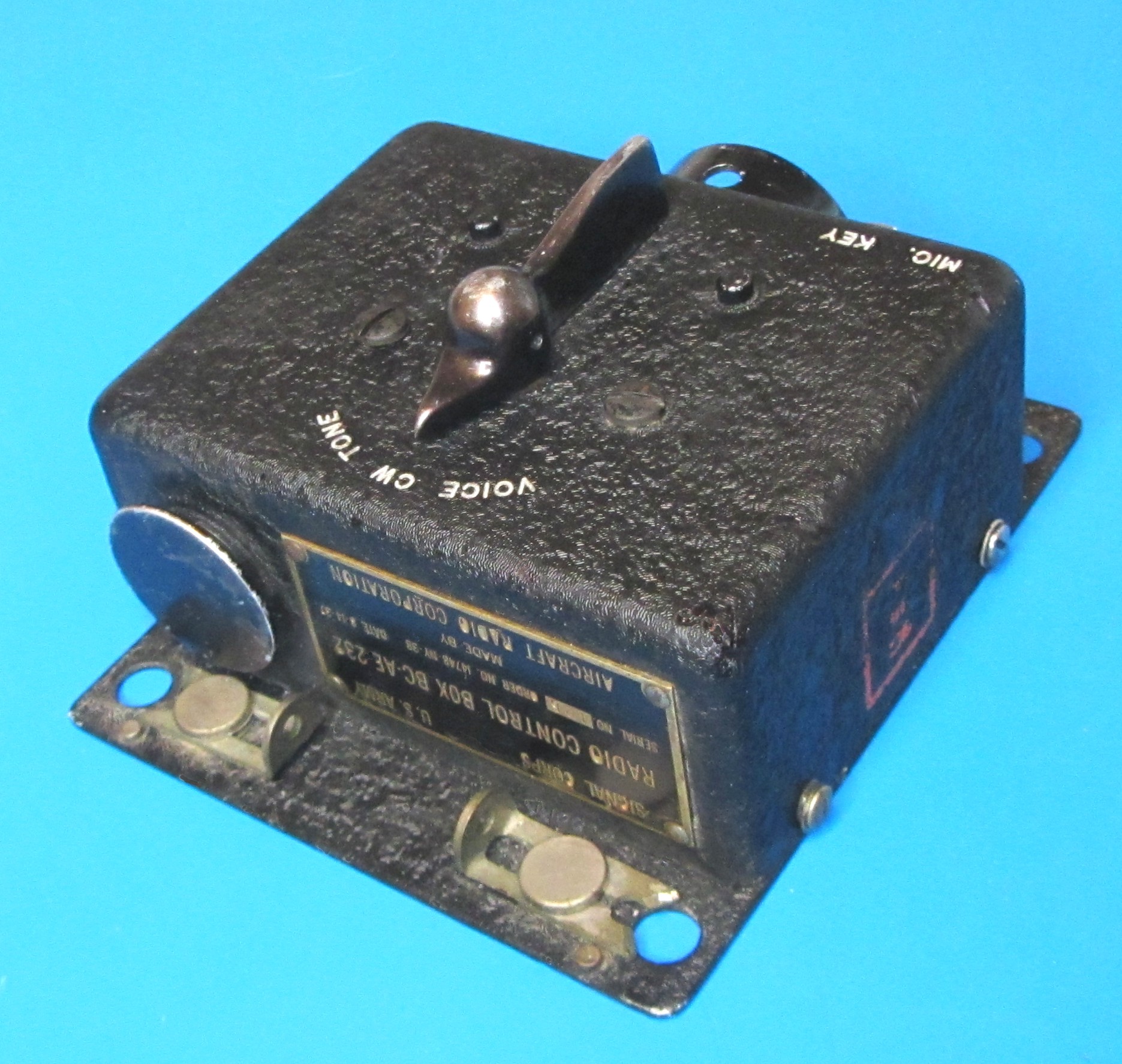
BC-AE-232 transmitter control box.
Among the tuning units available for this set is a curious example shown below for the transmitter that covers the 4,000-5,000kHz range, but can rely on a crystal to establish
a specific operating frequency within that range. If the crystal is plugged in, the frequency control on the transmitter doesn't affect operating frequency any more,so
the full range of the tuning unit is limited to the crystal frequency of choice.
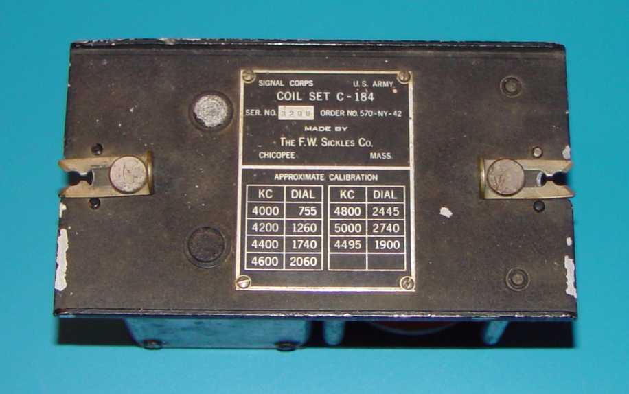
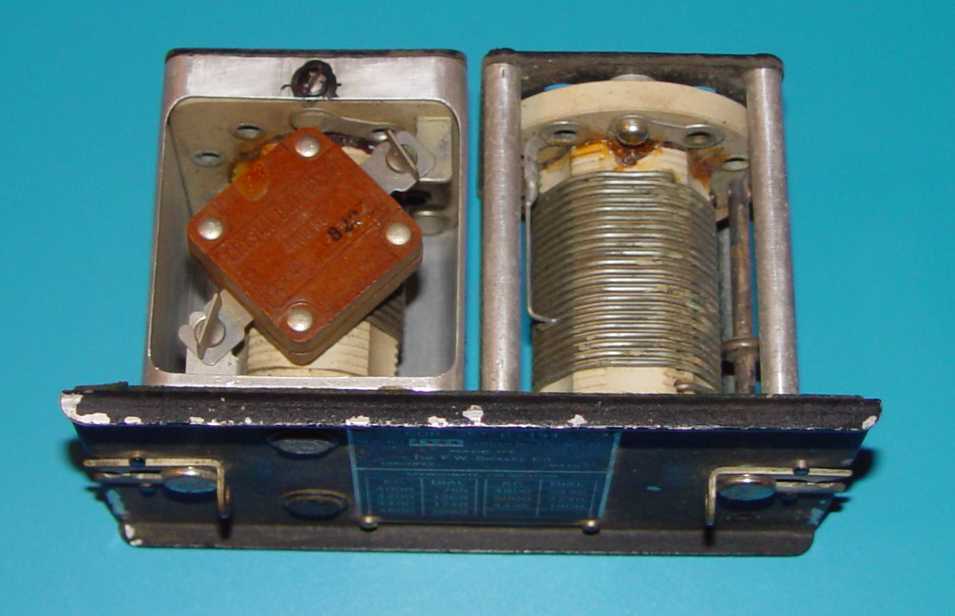
C-184 transmitter coil set. Unlike the other coil sets of the time, this one was apparently not manufactured exclusively by ARC or Western Electric.
The crystal itself has an unusual
DC-10 case that is retained in the circuit by two tiny wingnuts. The frequency is 4,495kHz, a tower guard frequency
for USAAC and USAAF aircraft in the
late 1930s and up through the war. Its issuance suggests it may have been created primarily for training aircraft,
to avoid giving the student yet
another thing to keep track of and potentially cause a dangerous situation.
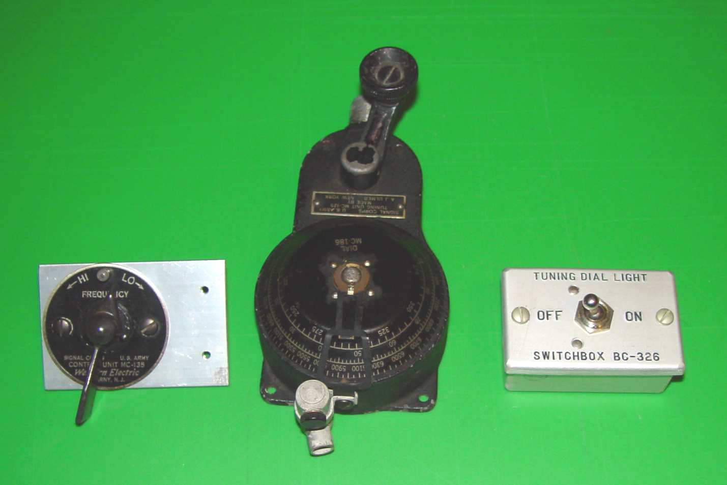
Receiver tuning head MC-125-A with M-185 tuning dial light and BC-326 dial light control box.
Also shown on the left is an MC-135 remote control to change receiver bands remotely.
The wire into the light requires a small nipple to provide strain relief and accommodate the #18 wire
normally used for this kind of current, but this nipple is usually missing and had to be fabricated for this set.
The light is a 3 volt LM-32 (industry 323) that was powered from either a vibrator supply called an "auxiliary box" intended
primarily for the 110 volt cockpit UV lights, or through a dropping resistor in the BC-326 tuning dial switch box.
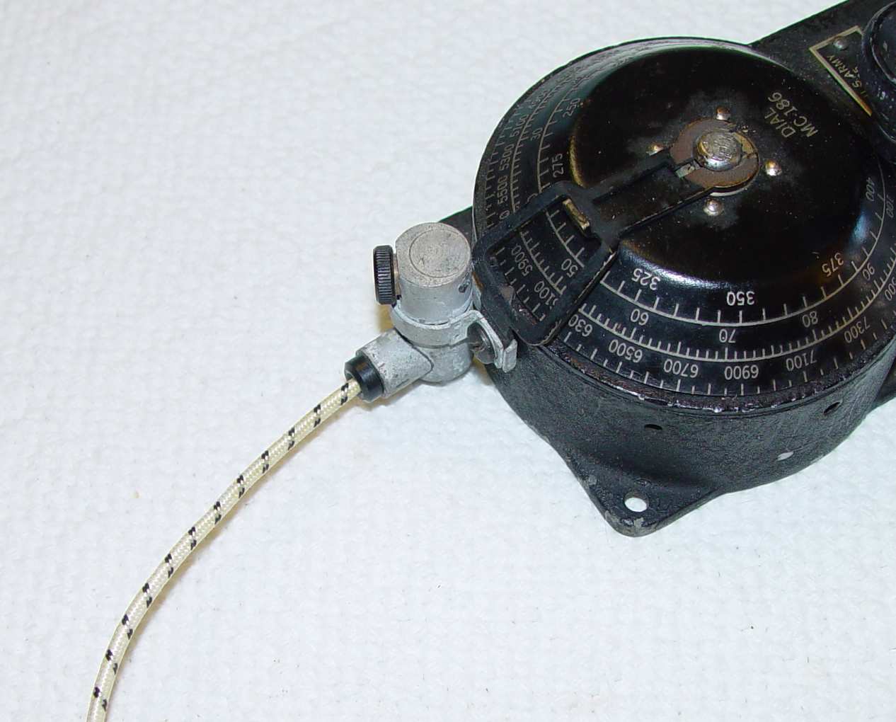
Not shown are the flexible MC-124 and MC-134 "speedometer" cables on the drawing below, used to tune the receiver or switch bands.
They are covered in some detail here. By the way,
Dave (AB5S) pointed out that with a typical 2-3 foot cable, the MC-135 needs to rotate almost a full 180 degrees either way from top to switch bands
in a dual band coil due to the torque required by the multiple ganged switch. The cable has some torsional "give" to it with anything over 6".
That means you have to plan its location carefully to allow your hand (and the lever) to rotate that much without bumping into something else. It also means that for longer runs
you must provide a solidly mounted Adel clamp as frequently as you can along the cable to reduce movement.
The drawing below shows the wiring diagram for the set using an alternative aircraft junction box (called a connector panel),
intended for a small cockpit like a fighter plane or trainer. This is used in place of the TM-AE-172 junction box that was
originally designed for larger multiplace aircraft, where conduit runs would be longer and the controls would be placed some
distance from the junction box. Later in the war, this use of a custom junction box seems to have become more the norm rather than
using the "official" TM-**-172, but a lot depends on the point in the war that one is considering. Given the small size of the
1930's bay, it made more sense to use the approach of the fighter version, shown below the schematic. Also note that wire and terminal numbers in this
diagram aren't all correct for an -AE- or -AG- implementation of the junction box, which changes the seven pin PL-104 on the receiving control
box to a six pin PL-65, for example. Subtle differences like this one can cause a lot of hair pulling time in final startup.
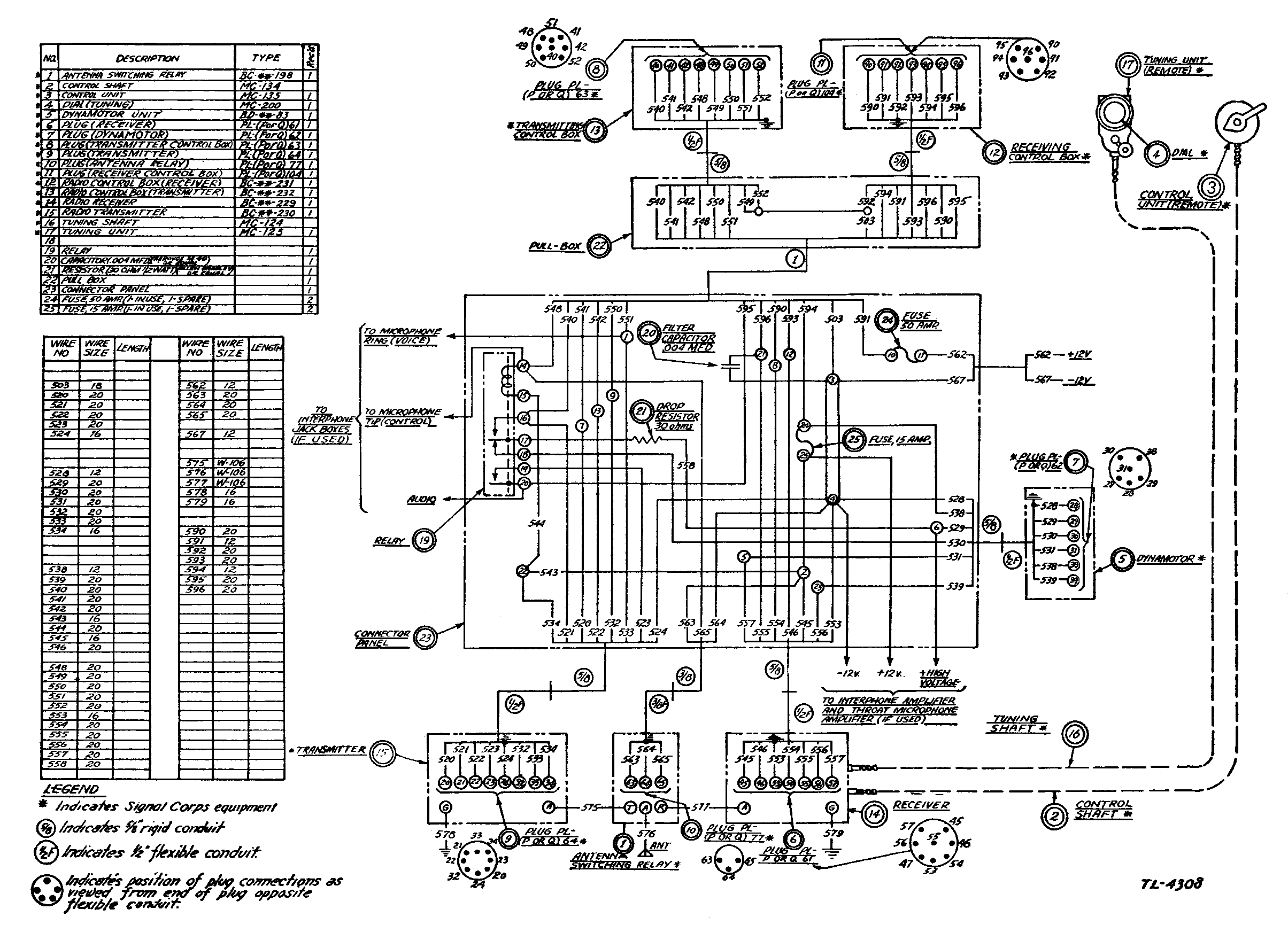
SCR-183 junction box (fighter aircraft version) system wiring diagram.
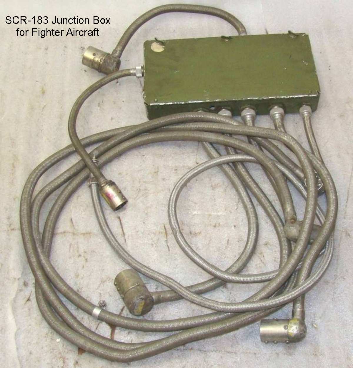
SCR-183 junction box (fighter aircraft version). All the cable lengths are sized to accommodate a physically small installation.
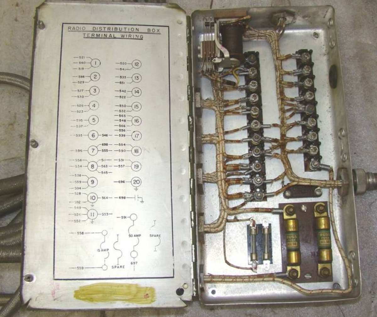
SCR-183 junction box interior (fighter aircraft version).
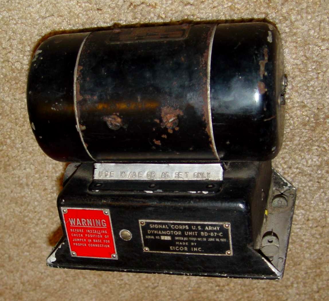
BD-87-C dynamotor. Note warning tag on the mounting strut.
Finally, to close out this little foray into the set being put together for the "flight deck", is one last oddball component - the BC-216 microphone amplifier.
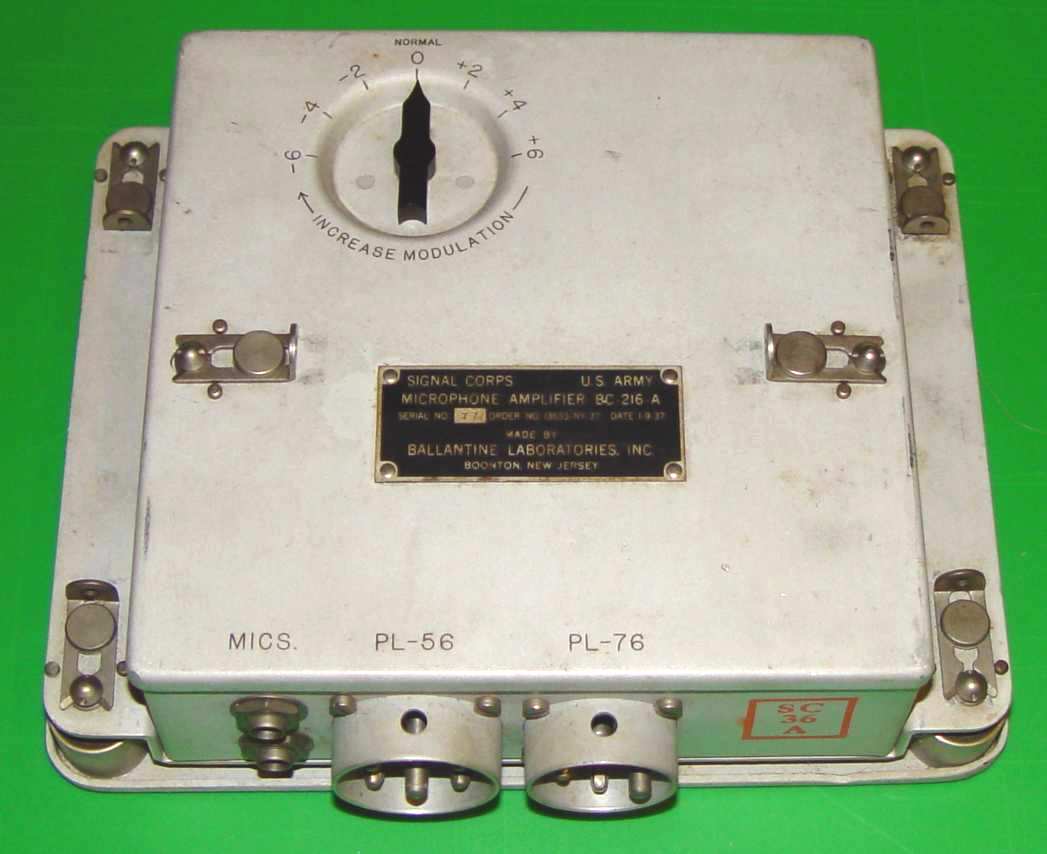
BC-216 microphone amplifier for dynamic microphone
This last item is actually an add-on to the RC-15A interphone set
that will be a part of the SCR-183 operational system here on the "flight deck". Since the dynamic mics for which it was designed are primarily
throat microphones, the primary use for this preamplifier will actually be to help salvage some of the sensitivity of 1930's era carbon microphones
(like the venerable T-17)
whose carbon granules have become largely cemented to one degree or another over the years. A minor reversible tweak to the jack box is all that is
necessary to provide current for the carbon microphones - that current is not supplied by the BC-216 because dynamic mics don't require it.
The "Kreusi Type" Radio Compass
Demonstrating how easily it is for these projects to get out of control, I recently picked up a compass modulator with a 1935 date, primarily because
the tag said it was designed to go with
the BC-AE-229 receiver! As most projects that start with a single piece usually do, that forced me to look for the
Fairchild E-4 loop antenna that went with it...more on that later.
The photo below shows the ensemble in its initial rough state.
Pictured below is the modulator and BC-AE-229 in two different aircraft, the first a Boeing BT-9 trainer and the second the Boeing XB-15 prototype. Note the BC-AE-229 to
the right of the E-4 Kreusi compass modulator in each photo, connected with a short piece of tuning cable. The receiver and modulator were tuned simultaneously by the same control head.
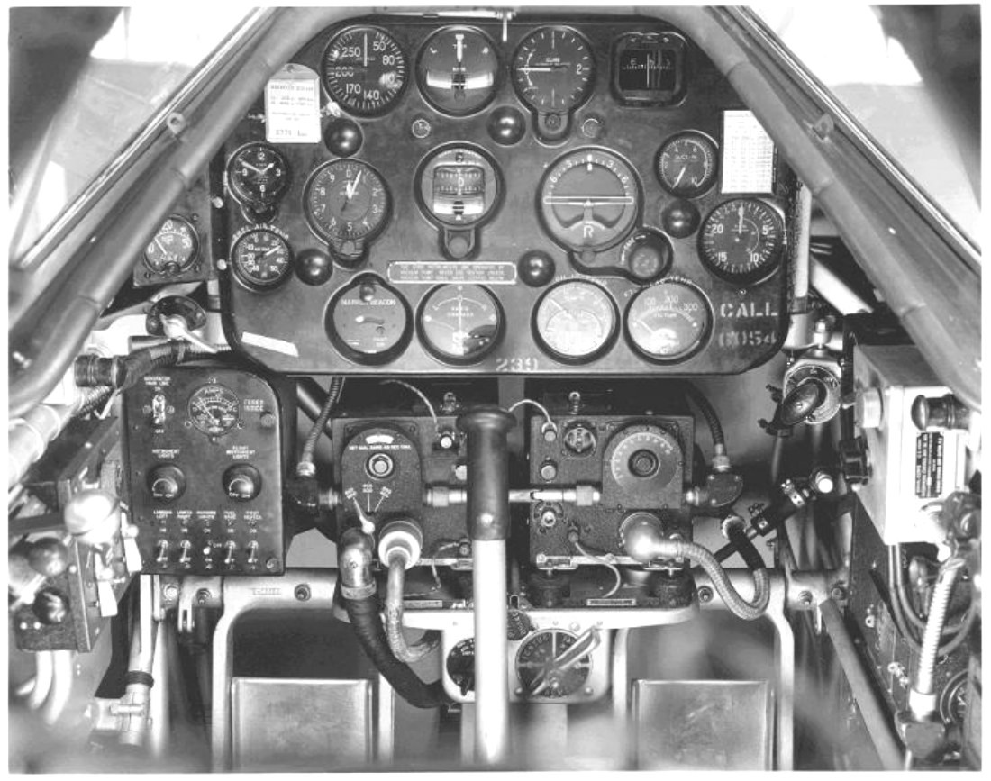
E-4 compass modulator in the BT-9. Typically in a single or dual place aircraft the entire plane would be steered from left to right and back again until the meter in lower
center was indicating a balance.
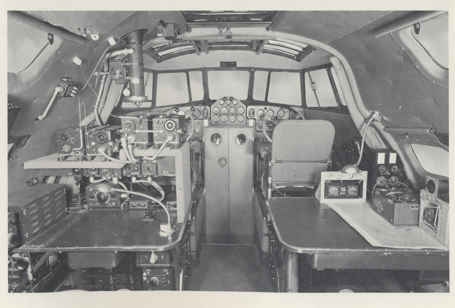
E-4 compass modulator in the Boeing XB-15 prototype. Here they used a rotating E-4 loop column support with slip rings to avoid having to rotate the whole aircraft to get a bearing.
The left/right meter is suspended on the side of the loop column. Ergonomics for the poor radio operator seem to have been neglected - he must stand up and reach over equipment and
the operator's desk to rotate the loop and read the compass angle, a problematic task in rough weather.
Below are some photos of the modulator (basically a left/right signal strength device using
a balanced meter to indicated when the loop field was centered on the transmitter being DFed.) The improvement mentioned on the nomenclature tag
was the addition of a sense antenna, attached to the "A" terminal on top. If connected to the command or liaison antenna, a switch on the control box evidently
allowed normal use of the BC-**-229 receiver for communications. The "R" terminal goes to the BC-AE-229 receiver.
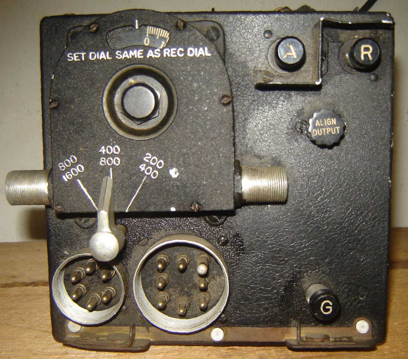
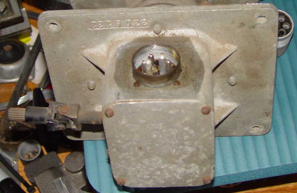
Front view, E-4-AE compass modulator. You will notice the accursed internally threaded connectors that were favored by the ARL engineers for navigation designs beginning
in the early 1930s, and finally died a ignominious death with the passing of the much later AN/ARN-7 automatic compass receiver when it was replaced by the AN/ARN-6.
I'm going to have to fabricate the two for the modulator. Luckily the AN/ARN-7 large connector shell is a perfect fit for
the larger connector, and only the insert will need to be made. The modulator also uses the same FT-100 shock mount as the shorter BC-AE-230 transmitter, saving
fabrication time there as well.
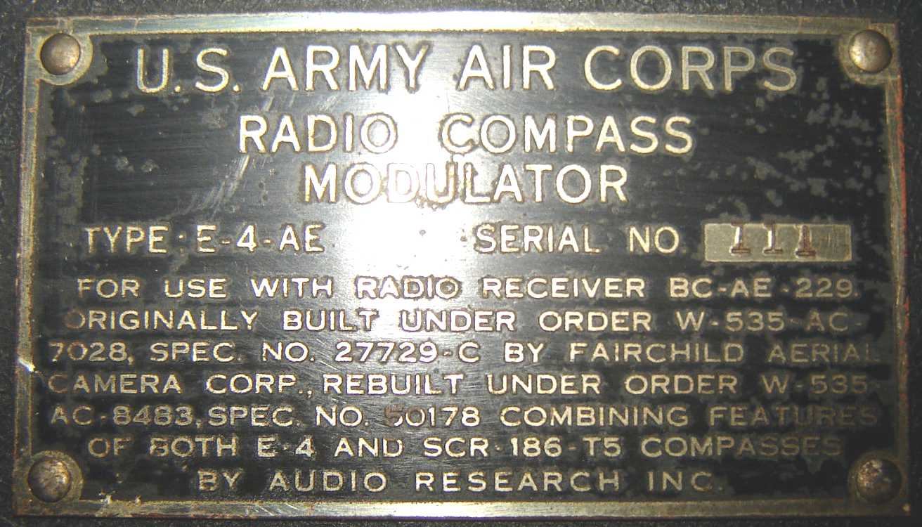
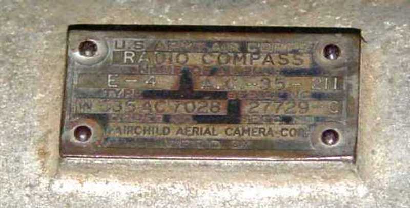
Nomenclature tag, E-4-AE compass modulator. It's fairly unusual to have this level of historical detail listed on a nomenclature tag, but it does provide
some excellent research data points.
The E-4 loop antenna for the E-4 system was made by Fairchild Aerial Camera Corporation, and shown below. The 21" diameter loop framework is made of
laminated wood from the ash tree, milled in an airfoil cross section and wrapped with doped aircraft fabric tape, then painted with blue lacquer. Fairchild
records on their history website that they delivered more than 10,000 of these loops from 1935 through 1947!

The spline drive exiting to the left controls a three position switch to select different portions of the antenna tuning range shown on the modulator. Presumably a drive cable leads
to a control head, and the control head then needs to select the same frequency range as on the modulator. There is no provision on the modulator to coordinate the two switches, which
clearly spells potential disaster in stormy skies.
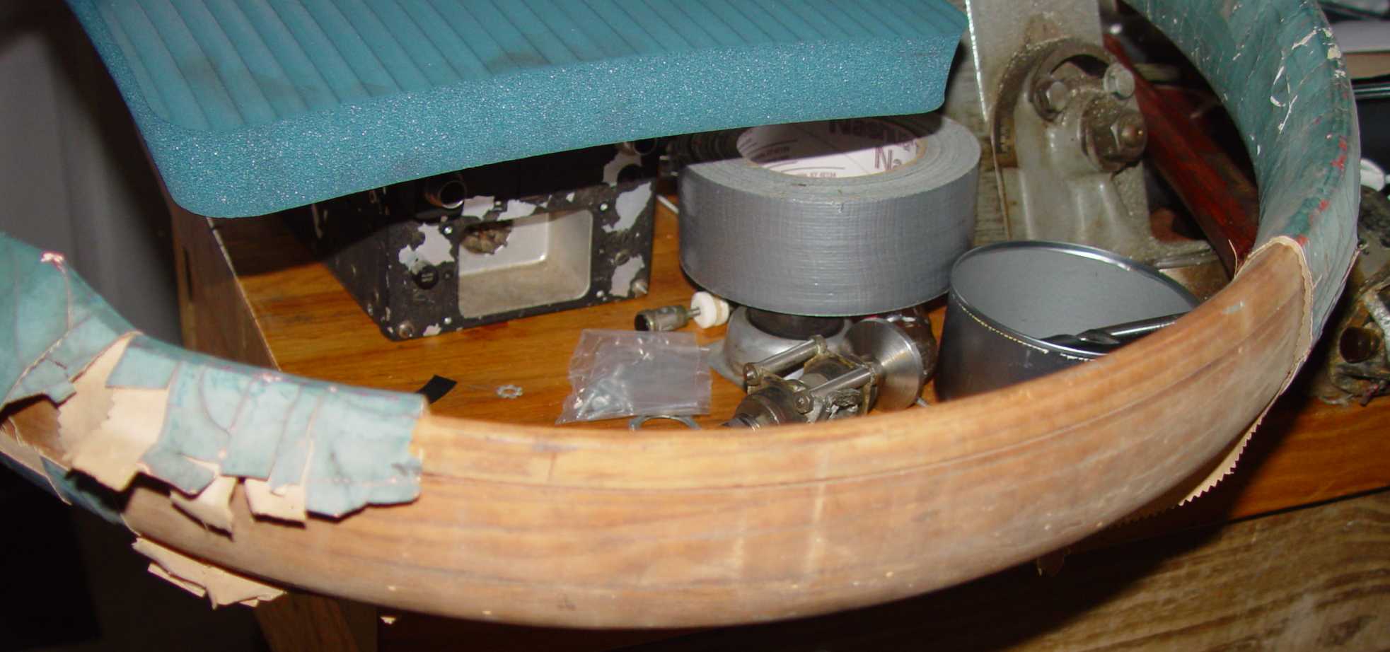
Top of the E-4 loop antenna. Some repair of the fabric will need to be accomplished and repainted with aircraft dope. Note the efficient use of workbench space,
with a command receiver, GO-9 top shock, duct tape, broken drills, and miscellaneous hardware quickly available for work when needed...
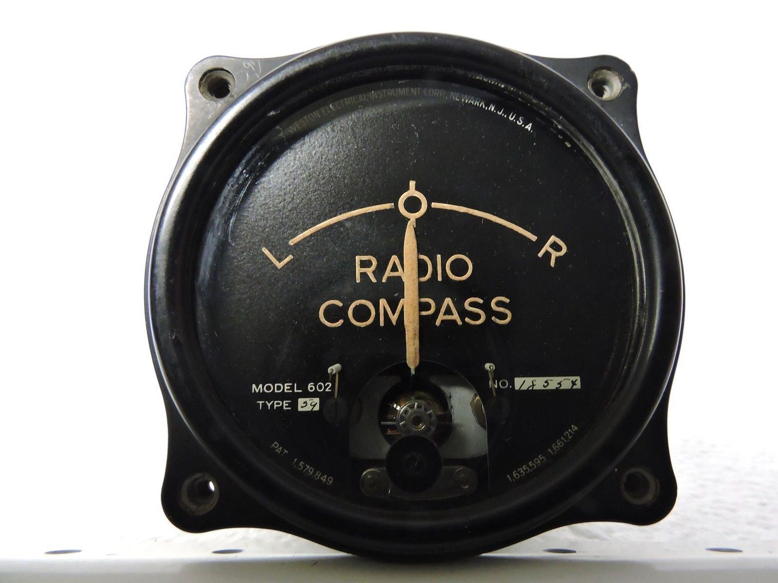
Left-right meter for the set, a Weston Electrical Instrument Corp. Model 602. Rotating the loop would allow centering of the needle, and then the relative bearing could be obtained.
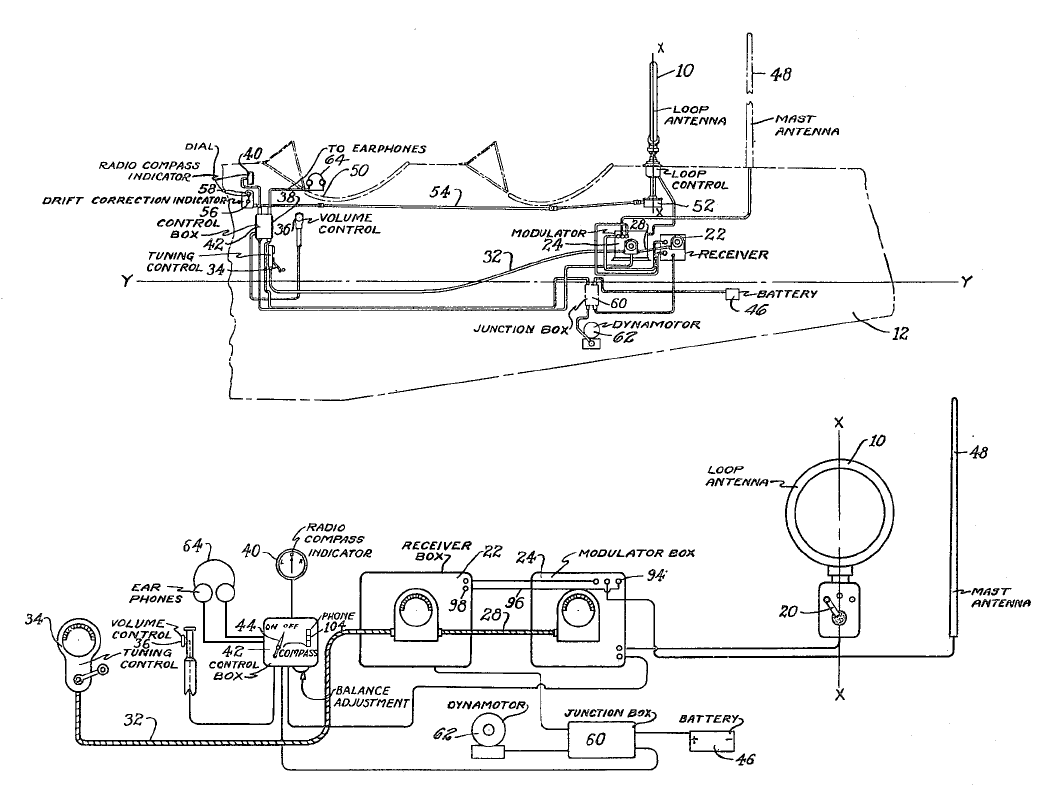
The missing pieces now are the control box, volume control, and some sort of manual for the system, though the patent has a good description of the circuit functioning.
I'll probably cobble up an ersatz control box for it - the patent drawings give a fairly good idea of its shape and content.
The modulator has a pair of VT-49s (39/44 pentodes) used as RF mixers that are modulated at an audio frequency by a 6A6 dual triode audio oscillator
(both halves are strapped together to emulate a single triode). The patent curiously identifies this tube as a small circle with a single sine wave in it, rather than showing the tube elements.
There is a balanced transformer in a box in the rear of the modulator that alternately enables one half of the
loop and then the other to make direction determination a bit faster and more stable. The patent description of this system is located
here. The system diagram from the patent is shown below.
The article below has an overview of the E-4 system.
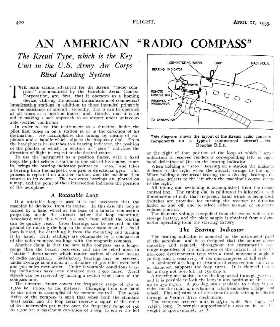
It's been interesting doing a little research on the Kreusi compass system. Geoffrey Kreusi was an engineer at the Army's Aircraft Radio Laboratory at Wright Field
in the early 1930s, and did a lot of work on blind landing systems, of which this equipment was a part. The mention on the nomenclature tag of the merging of E-4
and SCR-186-T5 sets led me to a cryptic remark in the first of the Army's "Green Books" ("The Emergency") that records "The radio compass, SCR-186, which had threatened
to split the Aircraft Radio Laboratory apart, had now become a dead issue, and the SCR-242 was the model in general use." Fascinated, I kept reading. It seems that a
turf war had developed within the Laboratory. As a result,
"The Aircraft Radio Laboratory went ahead with one form of radio compass, the Navigational Instrument Section with another. Very soon "a deadly serious fight was going on.
"Lieutenant Hegenberger locked up his part of the building, his engineers charging that Signal Corps technicians were appropriating their circuits; the ARL officers and
civilians, in turn, felt that the compass being developed under Lieutenant Hegenberger was actually their own, and that Army regulations clearly gave the Signal Corps
sole responsibility for such development. They pointed to Army Regulations 850-25. "While the Air Corps officers appear to be conversant with the provisions of AR 850-25," Rives
remarked, "they seem either hesitant as to how to proceed under them or else they do not desire to comply...." The Equipment Branch sought first to challenge this
regulation with another ("Under AR 150-5, the Air Corps as the using arm is authorized to carry on any purely experimental development which it sees fit to do...."), then
to change or even to ignore it, holding that the thing to do was to get aircraft radio and not allow regulations to stand in the way. Matters grew so strained that at one time
Rives went to the commander of Wright Field, Brig. Gen. H. Conger Pratt, and requested a court of inquiry into the charges being made against him and the ARL."
Needless to say, this small war turned into a larger one that essentially came down to the Air Corps versus the Signal Corps, and the solution reached in the early part of 1935
had some Solomonic aspects to it - the commanding generals involved believing that their decision had restored peace in their time. Sadly, it perpetrated the Signal Corps
dominance over air equipment development, a situation where the equipment began to fall woefully short of that being developed and produced for the US Navy air arm. It was never
really resolved, even after General Hap Arnold forced the Signal Corps to use Navy procured command communication sets rather than the substandard Signal Corps offering, renomenclaturing
them the SCR-274N (N for Navy), an action which must have rankled the Signal Corps brass but there was little they could do about it.
Return to 1930's Radio Bay