Notes on Bendix and ARC Flex Drive Tuning Cable Fabrication
This page is long, but is divided into four separate sections to help you focus on whatever interests
you at the moment. The headers are:
Bendix/Early Aircraft Radio Corporation Cables (the economy size cables)
Later ARC Flex Drive Tuning Cables (the "miniatures")
The Square Drive Components
Command Set Local Tuning Control
Just scroll down to the item of interest.
Bendix/Early Aircraft Radio Corporation Cables (the economy size cables)
In one of those "Oh no!" moments, some of us have discovered that the Navy ARB or RU receivers
(and some others which have early 1930s tuning cable drive components popularized by Bendix and ARC) used a slightly different
thread from the usual speedometer drive nuts in order to attach the cable to its control box or receiver. By WWII, Bendix navigation sets were probably the most
prolific user of this larger .450" outer diameter cable, though a few pieces of equipment like the aforementioned Navy sets and the USAAC SCR-183/283 stuck with
it as well. The smaller .335" outer diameter cable introduced about the same time as the ARC Type K command set equipment began to be used in
more situations because it was easier to run and weighed less.
Complicating the problem of using it today is that the thread size of the coupling nuts was not standardized. In the common pre- and WWII military
radio surplus, the coupling nuts on the military and commercial Bendix products generally appear to be identified by diamond knurling, and straight
knurling on the "other" style, which seems to be more closely associated with radar and other special equipment. The "military radio" thread is 5/8"-27TPI
(including commercial units used by the military), while the "other" commercial thread is 5/8"-24. The 27 and 24TPI nuts will *not* interchange without
cross threading, even though the internal coupling spline drives of both styles is identical. It's a shame, as I have seen a number of very nice 6" long cables that would be just
right for a collector's RU/GF or SCR-283 display but have the wrong thread on the knurled nuts. Interestingly enough, the 27 T.P.I. thread came from a 19th century
standard for gas light fittings. It persisted in electronic hardware in a number of places, including coax microphone connectors with the center soldered button.
Now, a 24 T.P.I thread is so close to 27TPI that there is a temptation to just use a pair of pliers to make the connection to a military or Bendix product,
but using that approach will distort the threads, and with a little bit of galling may make it necessary for you to saw it off if you want to decouple it...
The 5/8"-24 thread is typical of the speedometer cable threads of the era. The only way to know for sure which one you
are trying to match is with a machinist's thread gauge. It's easy to be misled by corrosion or gummy, dried out grease on the threads if you use the "try it"
approach with too much force.
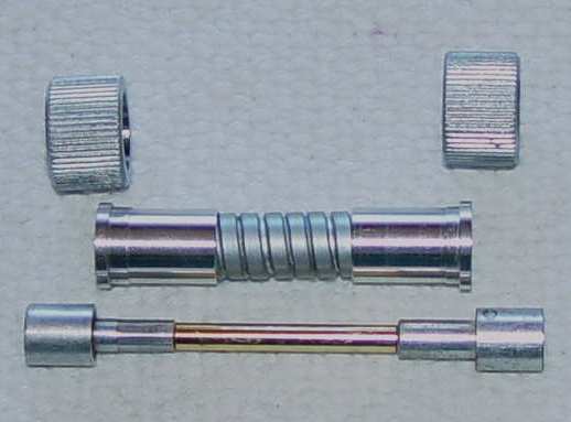
Piece parts for a typical drive. Note the straight knurled coupling nuts that are not correct for the military threaded products.
They are shown simply to demonstrate the two types that are floating around the surplus scene.
This particular cable only needed to be 2.5" long, so I chose to use a solid brass internal shaft rather than flex cable.
As for salvaging the spline drive ends from an old cable, it can be done. The actual spline coupling is usually no problem - it is removed with
either a 1/16" or 3/32" pin punch, depending on who made the assembly. It can get a little tricky trying to hold everything steady while you apply a hammer
to the pin, so I made up a little tool out of some 1" steel bar stock that uses a threaded steel screw with a short 1/16" diameter hardened nub on the tip. The body of the tool has the
threads for the screw and a .100" diameter hole opposite that to accommodate the pin coming out of the shaft. There is a hole at right angles to the screw into which you insert the
spline drive. I also relieved one side of the tool at a 45� angle so I could see the tip of the screw and its relative engagement with the end of the pin.
You don't want to be inadvertantly trying to hollow out a hole in the body of the spline simply because because you couldn't see that the tip isn't directly over the end of the pin...
You only need to get the pin moving a small amount before it can then be easily driven out the rest of the way with a conventional pin punch and bench block or other solid backing.
By the way, I have to say I don't much like the deformed pins or sometimes taper pins used for this purpose. If you do any repetitive work on tuning cables, get a supply of short roll pins
and enjoy the ease of installation and removal forevermore.
A greater difficulty comes in removing for re-use the nickel or cadmium plated brass adapter that gets
crimped onto the end of the flex drive cable. It is *not* a trivial operation to remove the bundle of spring steel strands from that adapter.
The simplest method is with a lathe, starting with a rigid center drill to begin excavating the tightly crimped bundle out of the
crimped cavity. Then you continue with a carbide drill to the final depth of the cavity. You need carbide because the spring steel
strands are hardened and will come out in tiny pieces that can tear up a conventional high speed steel drill bit. You also have to watch for a tendency for the drill to wander sideways and
enlarge the cavity. Frankly, I've given up trying to reclaim them - it takes just a few minutes to make a fresh one on the lathe.
A good grade of epoxy will hold the flex drive cable quite nicely if you clean the cable end of all grease and oil.
Most of the time you will still have to get the knurled nuts off the cable and shorten the sheath to the desired dimension for your particular
installation. That's not hard to do - a 1/16" thick abrasive cutoff wheel is the easiest method for both sheath and inner cable and usually won't unravel the spiral sheath as
sometimes happens with a hacksaw. If you want to be sure it won't unravel, use the Philco Services approach mentioned below and solder it before cutting.
Now, depending on how the original ferrule was attached, you may need to make at least
one new ferrule to crimp or epoxy onto the sheath. (Don't forget to put the coupling nuts on first! I can't begin to describe how irritating it
is to discover you've assembled the cable without them or with only one of them installed, or with one of them installed backwards...) I have
seen steel ferrules that were soldered onto the sheath, and you can sweat those off with a small torch for reuse.
I usually spray paint the sheath with chrome bumper spray, then wipe it down a week or so later with an old
undershirt to dull the shine. It gives an excellent replication of Type I cadmium plating without the mess and toxicity, and won't darken
over time like the real cadmium. Don't forget a drop of anti-sieze compound on the threads of the knurled nuts. Aluminum threads against
aluminum threads is a good way to experience the wonderful effects of galling and resultant frozen fittings.
Below is a sketch of one version of the ferrule - the one shown in the photos. Since 90% of tuning cable work around here seems to be
shortening existing cables to meet a particular dimension, you should be aware that there are variations in sheath diameter
(including some cables made from the smaller command set sheathing) and length. The left end dimensions should be fairly standard for the
Bendix style piece parts, but it's a good idea to try and match the one on the end you are saving just to make things look halfway decent.
I use the sketch below primarily as a template to make changes based on the particular cable I'm working on. You can make pencil changes
to a printout to match your particular situation.
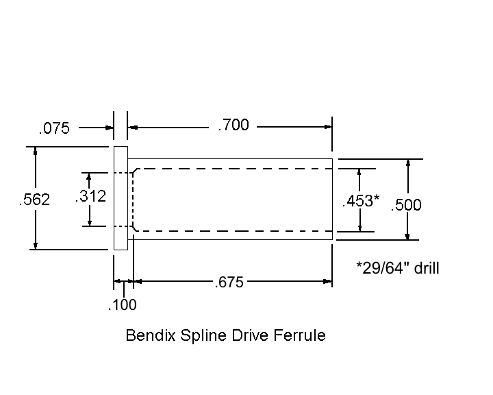
Sheath end ferrule sketch with typical dimensions
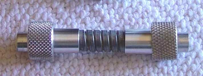
Completed assembly. Note the diamond knurled coupling nuts that are correct for the military equipment.
There are a couple of things to rememember as you assemble these cables. First is that the ends are not really bearings per se - the
spline couplings are held in a floating position by the male spline, while the sheath is held concentrically by the thread on the radio or
other device. The back edge of the spline coupling is the only bearing surface that occasionally rubs on the ferrule, and a drop of grease
is all that is necessary. The internal drive cable needs a very light coat of grease, mostly for curves where it is forced against the
sheath, but it is a very loose fit insde the sheath, so not much is needed unless you enjoy the sight of it oozing out of the sheath
spirals. The sheath is not a classic torque tube, which is to say it does not transmit a counter-torque from the drive device (the airframe
accomplishes that) so the ferrules don't have to be crimped to the sheath with significant force. I've even run into a couple of
examples where the ferrule was simply slipped onto the end without any mechanical bonding whatsoever, and presumably the cable still
accomplished its function, since they were removed from old aircraft! If you decide to mechanically stake the ferrules rather than using
epoxy, you'll have to use a sturdy mandrel inside to avoid collapsing the sheath. See the Philco Service sheets mentioned below.
The inner cable deserves a bit of thought as well. This cable is comprised of two separate sets of twisted strands, one set twisted in one
direction and the other set twisted in the opposite direction. This give the shaft its flexibility while maintaining torsional stiffness to
minimize backlash. A frequent approach to minimize the tendency to unravel is to clean the area to be cut with a good solvent
and apply solder to the phosphor bronze cable before you cut it. See the Philco Services link mentioned below.
Soldering will hold everything in place after the cut, and also provides a pre-tinned surface if you decide to make the spline adapters out of
brass or steel. I prefer stainless to eliminate the nickle plating step, so I just epoxy them onto the cable, but brass or steel material allows you
to sweat them on to the ends.
More detailed instructions on fabricating these cables is located in Philco Services Cable Fabrication.
One note on the Philco assembly drawings - of all the cables passing through here, I have never seen any thrust washers between the female splines and
the ferrule. That doesn't mean they were never installed - just that they don't seem to be common on the surplus samples I have seen to date.
The same warning applies to fabricating the spline adapters as to the above ferrules - measure your female spline couplings before machining the adapters,
as there are a few variations between manufacturers. Some of the female spline couplings have larger inner diameters where the
spline adapter fits into it, requiring a step up in the adapter to fit. Some are soldered into the spline, Others use a drive pin to attach.
Here is one example:
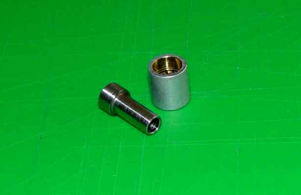
Typical stepped Bendix spline adapter before cross drilling for roll pin
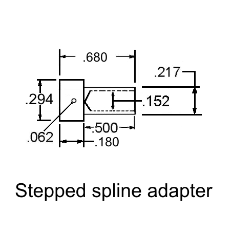
Stepped Bendix spline adapter sketch with typical dimensions
Below is a sketch of another typical spline adapter for the .450"OD cable. They are the same as the ARC 3406 on the command set cables, as one can
see from the next section below. Another example can be seen in the photo in the square drive section
below. Moral of the story: obtain your female spline couplings first, then machine the adapters to fit.
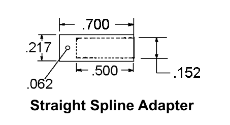
Straight spline adapter sketch with typical dimensions
Finally, for completeness, here is the knurled coupling nut that holds the whole assembly onto the radio or control box.
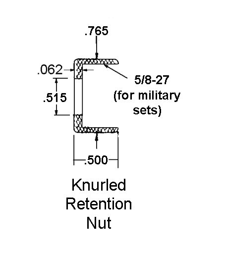
Knurled nut sketch with typical dimensions
Later ARC Flex Drive Tuning Cables (the "miniatures")
This cable was used on all the famous "command set" equipment in WWII and beyond, and is sort of an evolutionary development. It uses
precisely the same ~.148" diameter internal speedometer drive cable as the larger Bendix style above, but has a smaller .335"
diameter outer sheath. Makes you wonder why they ever made the larger .450" diameter cable sheath in the first place...the internal
drive cable really rattles around inside in that older standard. Below are most of the dimensions needed to make the piece parts of the newer cable.
Be aware that I have found the notes for sizing the length to be somewhat problematical. If you use 3/8" longer per foot for the sheath ("casing" in the note)
than length of the drive cable (the "shaft") as it is written, the drive cable may end up too short to install the second spline on the end, especially if
the sheath is not pulled to its maximum length to allow for the later later compression that is implied by the note. A lot will depend on the specific construction of the outer sheath,
and its condition - an old, corroded sheath will not generally compress and extend as much as a new one will. While the outer sheath does "accordion" a small amount,
with shorter assemblies you may end up on the short end of the stick. Using that factor (3/8" longer per foot) for the drive cable
provides an average fit for longer cables snaked through a lot of turns in aircraft, but sometimes forces the inner cable into a sine wave configuration within the sheath
if the cable is reasonably straight, so like much in life, "it all depends..." I much prefer the Philco approach, which is to cut the outer sheath to the correct length and
install it in your final configuration, then temporarily install, mark, and cut the inner drive cable to the perfect length. That may or may not match the ARC general
guideline but will make tuning easier with less friction because everything is in its final relaxed state.
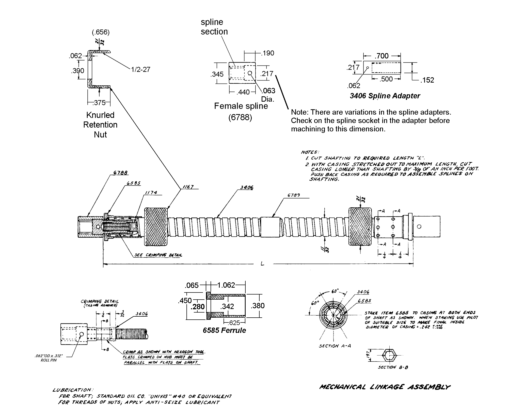
"ARC-5/SCR-274N/ARA" drive cable details. Note that these are guidelines and should be compared with your actual fittings.
There are minor variations with different manufacturers and time frames of production. The 6788 female spline, 3706 spline adapter,
and a portion of the drive cable (1174) are shown below (marked "274N parts") to provide a comparison with the other cables mentioned here.
Note that I prefer to use epoxy rather than crimp the spline adapter onto the cable, but crimping is the "official" solution.
The Square Drive Components
While we're at it, I should mention the Navy RU and Signal Corps SCR-183/283 receivers had a square drive that used the smaller diameter
cable, both for a loop/long wire antenna switch and for the dual band coils that allowed two bands to be covered by one receiver.
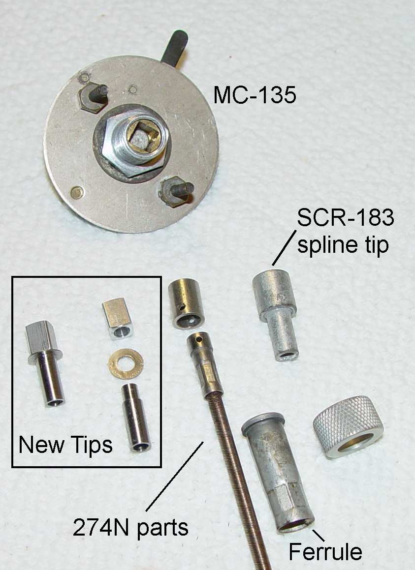
Drive ends for RU and SCR-183/283 dual band coils. The MC-135 is the Army nomenclature for the control,
while the Navy refers to it
as a ***-23054, but they are otherwise identical. The Army nomeclature for the cable assembly
is MC-134, usually stamped on a clip that wraps
around the cable. Paradoxically, the smaller .335" diameter outer sheath used
for the later command sets is employed here. The new tips are shown,
along with equivalent SCR-274N/ARC-5 drive parts
and the larger Bendix spline adapter detailed above.
The thrust washer is not always used on every example I've seen, so apparently it isn't essential.
The tips for these require some different dimensions. Sadly, you can't just use 1/4" square stock out of the box for the tip - the broached
socket in the fittings being switched were made exactly or slightly under .250" for some unknown reason, requiring you to remove .005" to have a
reasonable fit. Makes me wonder what they were thinking... You don't have to use a roll pin to put the tip and adapter together - they could be made in one piece from
steel or brass and then soldered to the cable if desired. Note the procedure for preparing the cable for soldering in the Philco Services pamphlet mentioned above.
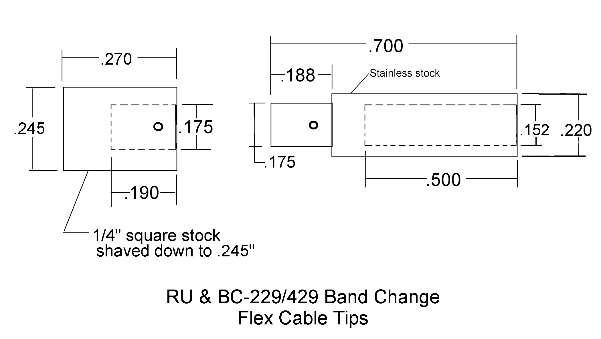
Drive tip and adapter sketch with typical dimensions for square drive components.
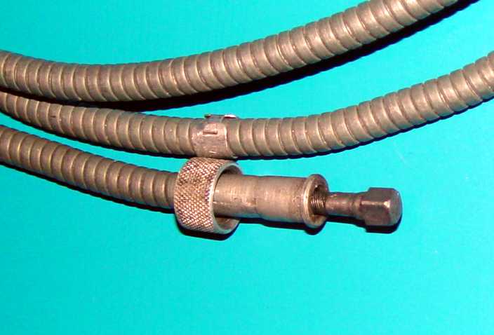
An original MC-134 cable and tip - this one is one piece and soldered onto the flex cable.
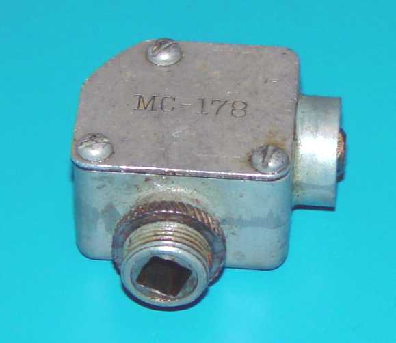
An uncommon MC-178 right angle drive to route the MC-134 cable with shorter bends where necessary.
This could be made up using an MC-136 right angle drive and replacing the spline fittings with a female
fitting from a scrap dual-freq RU or BC-229/429 tuning unit and fabricating the male with the right dimensions.
One of the unexpected surprises using this cable is that the coil boxes often have internal friction that make a cable longer than a foot
or so extremely impractical because of torsional give. There is a stop on the MC-135 and 23054 that prevents you from turning the control
more than 180 degrees either way from center, and that may not be enough to switch the coils completely. In my sampling of half a dozen coil boxes,
some were really bound up, to the point where they were
uncomfortable to move even with the little lever that is often installed on the coil boxes. Taking one of the coils apart showed the reason -
the switch mechanism is a circular piece of rough machined phenolic riding in Micalex bearings, neither of which have a particularly low coefficient
of friction. Add the vagaries of the long acetyl switch shaft that traverses all four of the coils, pressing the switch wafers radially this way and that,
and it's no wonder they are hard to turn after 70 years. Luckily, a spritz of Teflon dry lube and some exercise reduces the friction enough to
make the whole unit switchable by cable once again. Loosening of the mounting screws and gradual tightening to allow the coils to seek their own
center is a good idea as well. If all else fails, you can remove the detent mechanism on the end of the shaft before reassembly and get rid of
that friction. Unless you have a vibrating aircraft, the switch will easily stay in one position or the other without a detent.
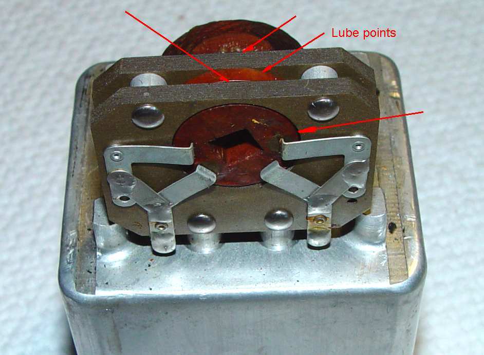
Locations of areas requiring lubrication with a Teflon based dry lubricant
Command Set Local Tuning Controls
Somewhat related is the local tuning control knob for the ARC-5 and related command receivers.
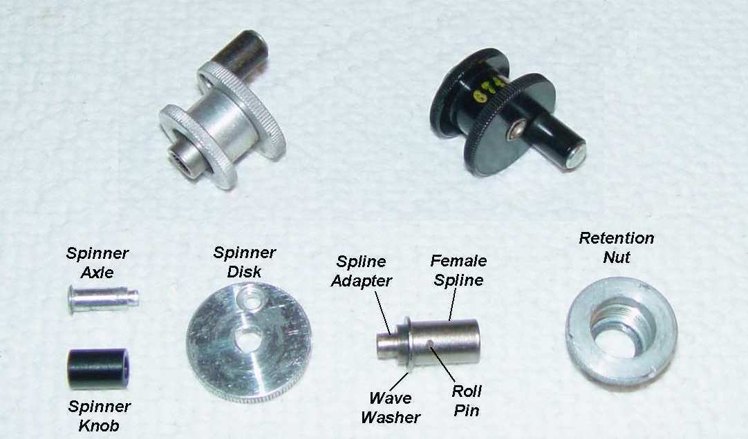
ARC 6743 Local Control knob assembled and disassembled.
Shown above is the 6743 knob that was used from the original RAT receivers to the end of the AN/ARC-5 series. The earliest ones were black laquered,
but with the introduction of the SCR-274N, they began to be made in bare aluminum. Below are fabrication details for the originals, but of
course changes could be made if one does not wish to remain "authentic" (whatever that means.)
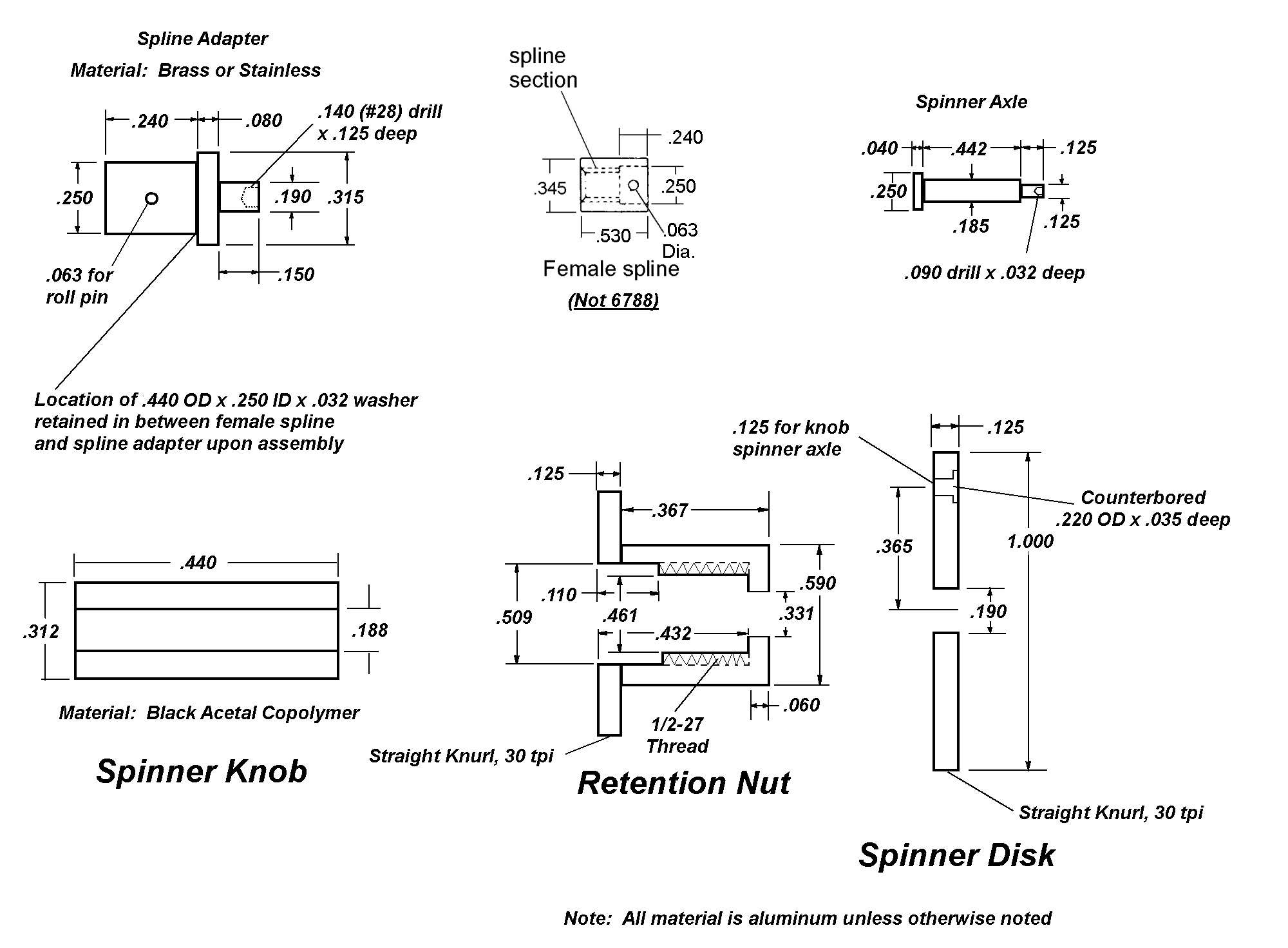
Exploded view sketch with typical dimensions.
Unfortunately, this assembly uses a different length female spline than the cables do. The more common (and shorter) 6788 spline can be used but
a collar would have to be made to make up the difference on the backside, and the diameter of the spline adapter might need to be reduced
from .250" to .217"...I have encountered both IDs in the spline. This reinforces the need to have the spline in-hand before launching
into machining any metal. The finish elevation of the end of the spline above the retention nut should be about .150" when everything is assembled.
Assembly is fairly straightforward but requires a sequence. The spline must be attached to the spline adapter with a 1/16" roll pin before
staking the spinner disk on the front. It is a lot easier to engrave the 6743 numerals on the disk before attaching it to anything.
I have encountered both flat and wave washers installed between the spline and adapter (the washer is not shown in the sketch above)
- it provides a lubricated thrust bearing surface for the whole assembly, so it is desirable. The spinner knob must be riveted onto the spinner disk prior to that.
Ideally the disk should be both riveted and staked onto the spline adapter. By that I mean a two step process - a drop of epoxy (too much and you may fuse the
whole assembly after it cures due to spreading to the bearing area), followed by gradual riveting with larger and larger center punches to
roll the edge of the hollow rivet over - that's the first phase. It's necessary to support the bottom of the spline and you can't use a five pound sledge
to do it - it's a gentle operation. Then it must be lightly staked. In the original that was accomplished with a three sided staking tool, but that requires
some fancy work on drill rod with a grinder. It is easier to take an old screwdriver and sharpen the edges at a 45 degree angle so that it fits into the drilled
out portion of the spline adapter. Two light taps 90 degrees apart will then stake the disk on in four places. The staking ensures that the disk won't rotate on
the adapter shaft in normal use.
There is a closely related local tuning knob that I have resisted including here because it is unquestionably postwar, but is so closely related that some
folks keep calling it a "command set", or "ARC-5" tuning knob. Just to clear up the misapprehension, throughout this website I have limited the coverage
to equipment built for WWII use (including things that were nomenclatured in WWII but produced later than the end of 1945). But it seems reasonable for an honorable mention.
The ARC 18802 spinner knob is one of those postwar transition pieces about which probably everyone would wonder, "why didn't they just make it like this in 1939?"
The answer is likely because the command receivers up through 1944 were not particularly stable enough to warrant it, but the three "Lock tuned (Circle S)" ARC-5 HF receivers led the
way to pressuring a better design of the local tuning knob. The photo below shows this tuning control alongside the WWII version.
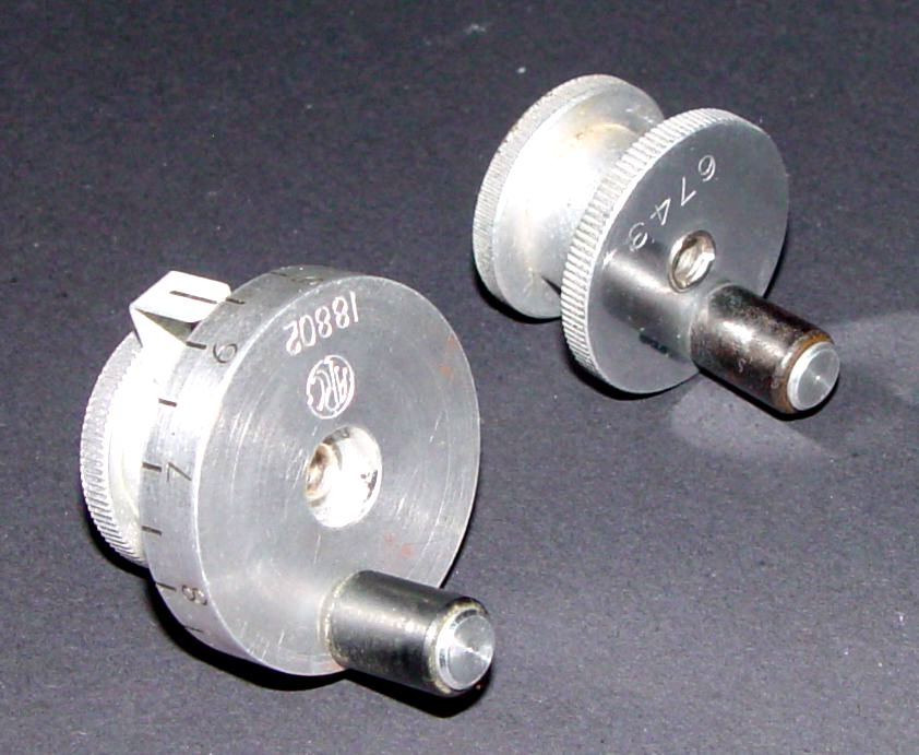
ARC 18802 local tuning knob next to earlier 6743 version.
The later knob uses the exact same parts in the rear as those in the 6743, staked onto the tuning knob with the same familiar triple staking tool marks, but makes the
knob thicker in order to engrave a set of numbers from 0 to 10. It adds a stationary fiduciary to the back of the knob, simply clipped onto the mounting knob with
a piece of what appears to be cadmium plated beryllium copper (it's non-magnetic, with a spring constant) to allow rotation and quick adjustment. It permits easy adjustment of the fiduciary to
accommodate receiver drift during warmup and use.
I will leave the decision of whether to use one of these on your own set to the discretion of the reader. They do look pretty sharp.
Finally for completeness, ("It's about time", most of you are likely saying under your breath), there are two controls on the lower frequency AN/ARC-5 receivers which
permit switching between a single wire antenna and a loop antenna. Those are covered in some detail Here.
Return to Garaj Mahal