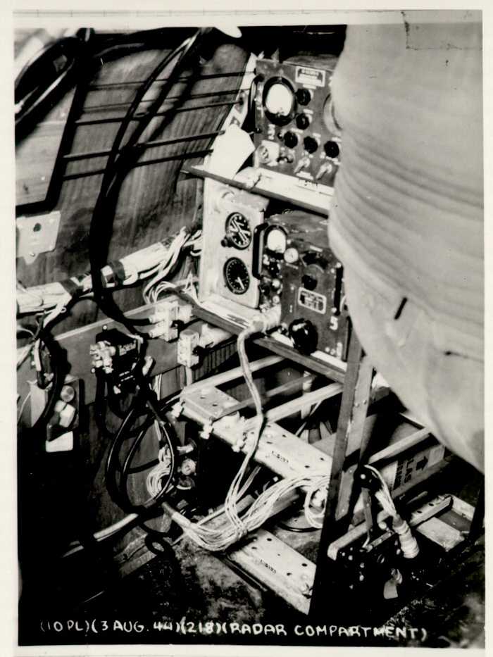
Countermeasures Position, normal B-29 Installation (early standard configuration)
The Radio Countermeasures Officer (sometimes called the RCM officer, or "Raven") was a late addition to the B-29 crew compliment. Their normal function was to identify, record, and counter enemy radar that might be illuminating the aircraft or squadron for fighter direction, gun laying, or searchlight pointing. The standard installation rack for B-29s did not have a lot of room for equipment, primarily because the rear upper gun mount took a good deal of room in the radar compartment.
In the case of the Enola Gay and her sisters in the 509th Composite Group, that primary RCM function was modified - at least for any actual nuclear weapon carrying missions. The removal of all gunlaying equipment in the Silverplate aircraft (except the tail gun) freed up more room for specialized equipment, and the suite carried by each aircraft depended on its function for any given mission. As a result, RCM equipment was constantly being installed and removed, even in the "pumpkin" training missions to Japan that used ordinary high explosives in single bombs with the outline of a plutonian weapon. Due to the high weight of the nuclear bombs, whichever aircraft was designated to carry the actual weapon was tailored with a minumum of equipment. Because the primary weapon fuse was based on a radar altimeter within the bomb, stray or deliberate radio transmissions from the ground at just the right frequency could potentially prevent detonation or set off the bomb as soon as internal timers and a secondary bank of barometric switches had armed it after leaving the bomb bay. The Countermeasures Officer in the aircraft with the weapon (Jacob Beser in the case of both atomic missions) was primarily responsible for scanning the frequencies between 390MHz and 430MHz and notifying the Weaponeer of the frequency and characteristics of any interference. According to Leon Smith, who designed the Weaponeer's control station, the Weaponeer could then choose between two sets of four fuse frequencies (each of the four AN/APS-13s were tuned to a slightly different frequency to avoid interference with each other). A fuse of the contact type was apparently considered for Little Boy as "salvage fusing", but the gun assembly method was essentially self-assembling on contact with the ground at high velocity after falling for six miles. A last resort contact fuse was reportedly included on the Fat Man weapon, because it was not self assembling due to its spherical construction with multiple fuses.
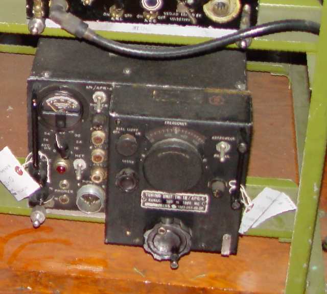
The primary instrument for detecting this potential interference is at bottom right in the above photo, called an AN/APR-4 receiver.
The Countermeasures Officer reportedly sat on the floor to operate this gear (an uncomfortable position to be sure), but the APR-4 was normally configured to automatically scan back and forth across a preset range of frequencies. This would allow
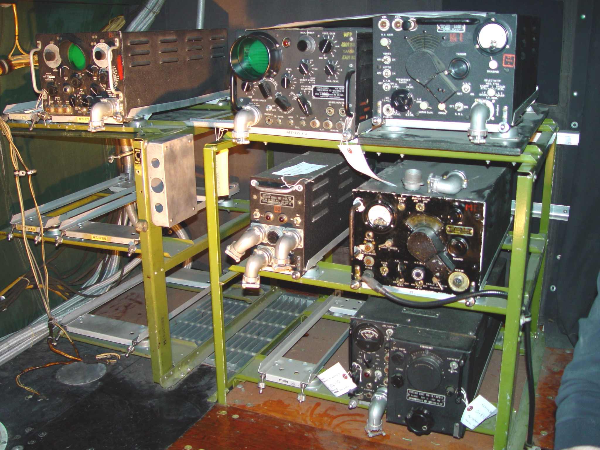
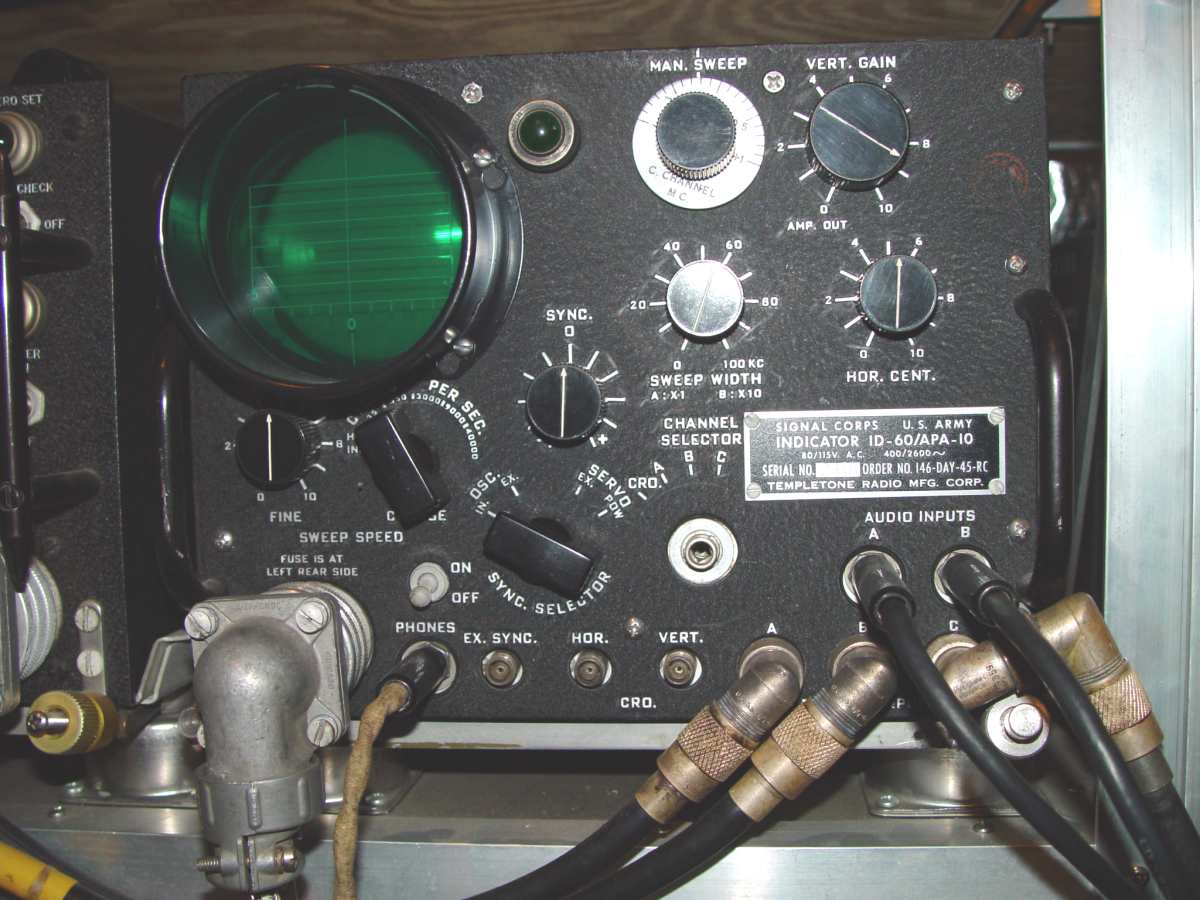
the officer to sit on the toilet seat to the left, (or after the war was over, a chair to the right of the radar operator) listening to the headphones and watching the panoramic adapter screen of the AN/APA-10
for any indications of interfering signals as they approached the bomb release point. The AS-114/APT blade antenna for this receiver was the result of a
voluminous search of photographs of the Enola Gay without result. It was finally spotted in a motion picture of the right (starboard) side of the aircraft while taxiing after returning from the drop.
The position itself may seem incomplete and missing a great deal of equipment, but in fact (for the Enola Gay on August 6th, at least)
it is shown fully configured before cabling - except for the recorder to record interphone conversations. This is based on a review of Flight Reports leading up to the mission.
In fact, what is actually an AN/ARR-7 HF receiver in the center has been removed because it had no documented installation date through August 6, 1945, nor antenna to support it. More of the empty positions were used when the aircraft was employed
in an instrumentation mode that supported the drop of three parachute canisters to measure the weapon yields. There was also room for eventually installing radar jamming equipment when there was an
anticipated threat, as there well might have been had it been necessary to continue dropping nuclear weapons on Japan to conclude the war. (But there is no official record of any jammers being installed in the bomb carrier on either the
Hiroshima or Nagasaki missions.)
The other pieces of equipment seen above are (from top left to right):
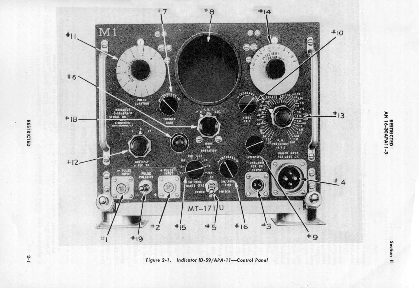
AN/APA-11 pulse signal analyzer, a specialized instrument that permitted detailed characterization of electronic radar signatures to reveal type and power.
AN/APA-10 panoramic Adapter an extremely useful visual presentation of all the radio signals within a given frequency band on either side of the frequency to which a receiver is tuned.
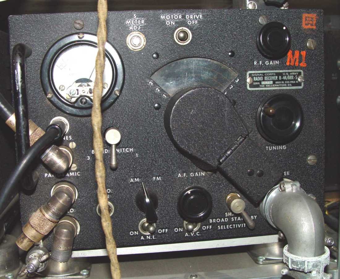
AN/ARR-5 VHF radio receiver. The AN/ARR-5 has since been moved vertically down to the rack below where the AN/ARR-7 formerly resided, in order to free up the green plywood board on top
for its original purpose, which was to accommodate odd shaped
pieces of equipment not designed to fit the standard ARINC mount used in the rest of the position. It had two canvas belts that could be wrapped over the piece of equipment to hold it in place without the security of the ARINC mounts.
On the Hiroshima mission it supported an RD-6/ANQ-2 Acetate disk recorder that Jacob Beser reportedly used to record interphone traffic on that day (see the middle of the page at "Recorders").
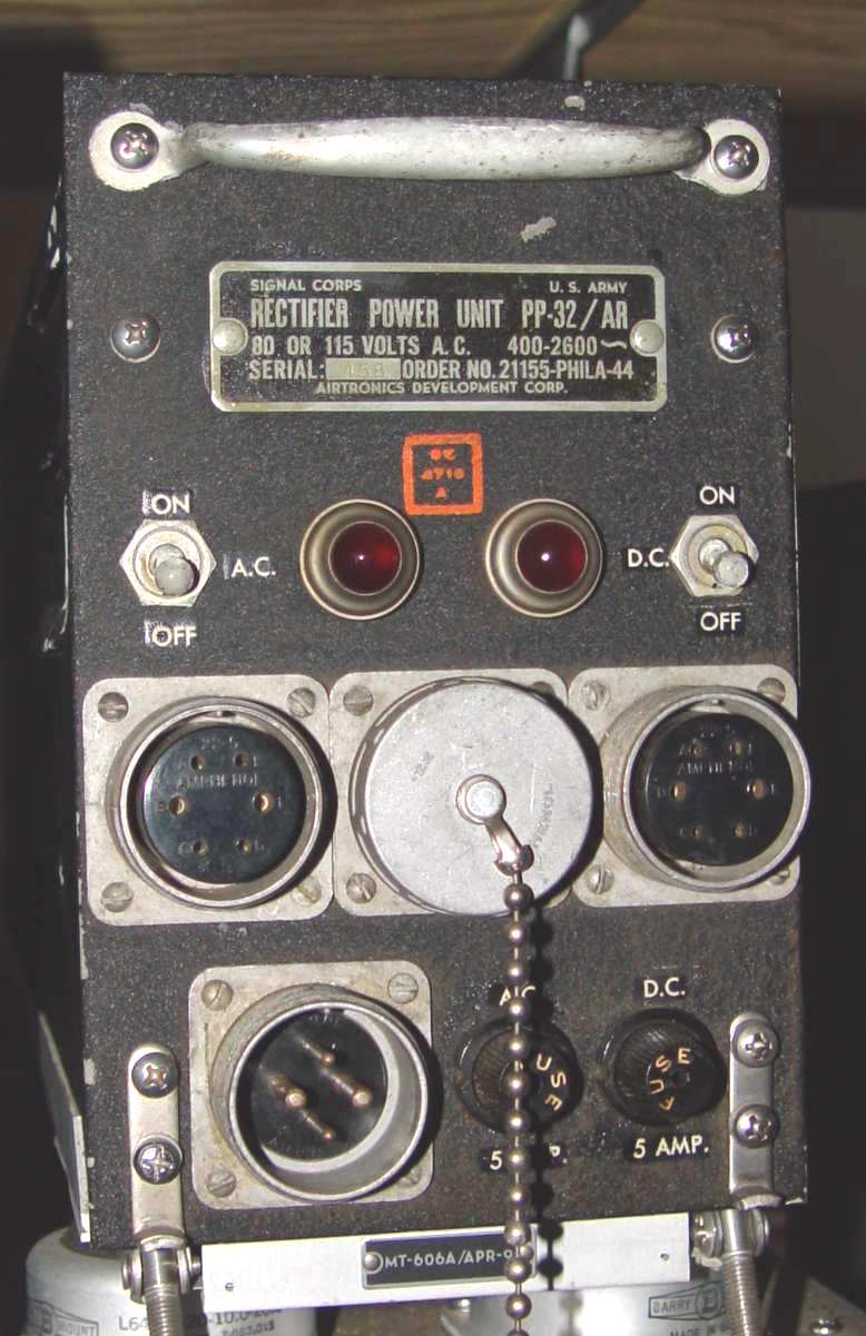
In the second row is a PP-32/AR power supply, used for the AN/ARR-5 receiver that ultimately migrated to its right. That receiver was installed to permit listening for the succesful deployment of three instrumentation canisters by the instrumentation aircraft (The Great Artiste on the Hiroshima mission.) (See more on this below.) The aluminum box to the left of the PP-32 is a junction box fabricated to the original specs that will be used to rewire the power and audio distribution circuits. It has since been painted the same olive green color as the racks.
Standard B-29 countermeasures positions only contained one vertical rack of equipment, shown above. However, a 509th mission was considerably different from those of its brethren.
A standard weapon drop envisioned three aircraft over the general target area at one time; the weapon dropping plane, an instrumentation plane, and a photographic plane. Ultimately,
any of the 509th aircraft needed to be capable of being configured to serve in any one of those roles. That is the reason that the Enola Gay installation may seem somewhat
empty - its spectrum management role on August 5th was limited to the weapon fuse frequencies and cross checks of other roles. By far the most equipment-consuming role was the
instrumentation aircraft. In addition to the equipment shown in Enola, it required a total of three VHF receivers to listen to the three air dropped canisters in the vicinity of
50MHz, as well as three recorders to record the overpressure signatures provided by the canister microphones. From this information and estimates of location of each canister with
respect to the weapon's detonation, approximate weapon yields could be calculated. As related in a fascinating LAUR (Los Alamos Unclassified Release) monograph by Dr. Glen McDuff,
three Hallicrafters S-36 VHF receivers were used in The Great Artiste to receive the overpressure waveform from the parachuted instrumentation canisters dropped prior to bombing,
but these required special non-standard wide mounts and were significantly heavier than their repackaged condition in the AN/ARR-5 version. The outputs of these receivers for the
Hiroshima mission were connected to three Dumont oscilloscopes of the type shown here, which in turn had three Kodak Cine E 16mm
movie cameras attached with light shielding tubes to record the oscilloscope traces. Since this laboratory system was physically large and somewhat unwieldy to set up, future missions
(had they been necessary) would most likely have switched to more available countermeasures equipment - three AN/ARR-5 receivers, three AN/APA-11 pulse analyzers, and either three radar
film movie cameras made for the APA-11s or possibly three AN/ANQ-1 wire recorders, given the results obtained from the first drop. That suite of equipment types in fact reflects the
expanded countermeasures rack configuration capability that exists in Bockscar today, the plane that flew the Nagasaki mission.
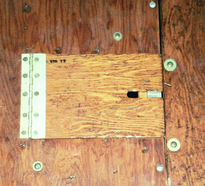
Simultaneous recording of three independent
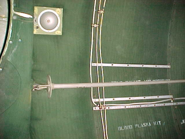
signals required a special antenna to be rigged from the belly of the aircraft, through a hole in the bottom of the radar compartment. Below are shown the hatch and antenna. It is very
similar to the antenna and procedure used by the Navy for their sonobuoy receivers in locating submarines. The antenna was too long to remain in place for landing. so it was intended to
be rigged and removed during flight. You can see it in the deployed position in the "Exterior Antennas - right side" page. On the Hiroshima flight it was
deemed necesary to deploy it prior to takeoff, so the antenna was shortened from a half to a quarter wavelength to avoid dragging it on takeoff.