Exterior antennas - right side
The B-29 had one of the most advanced set of communications and special avionics antennas on any aircraft
series in the war, though eventually most of the American inventory was similarly equipped. The intent of
this and the port side view
(See "Exterior Antennas - left side") is
to describe the function of these antennas in some detail.
 Starboard antennas
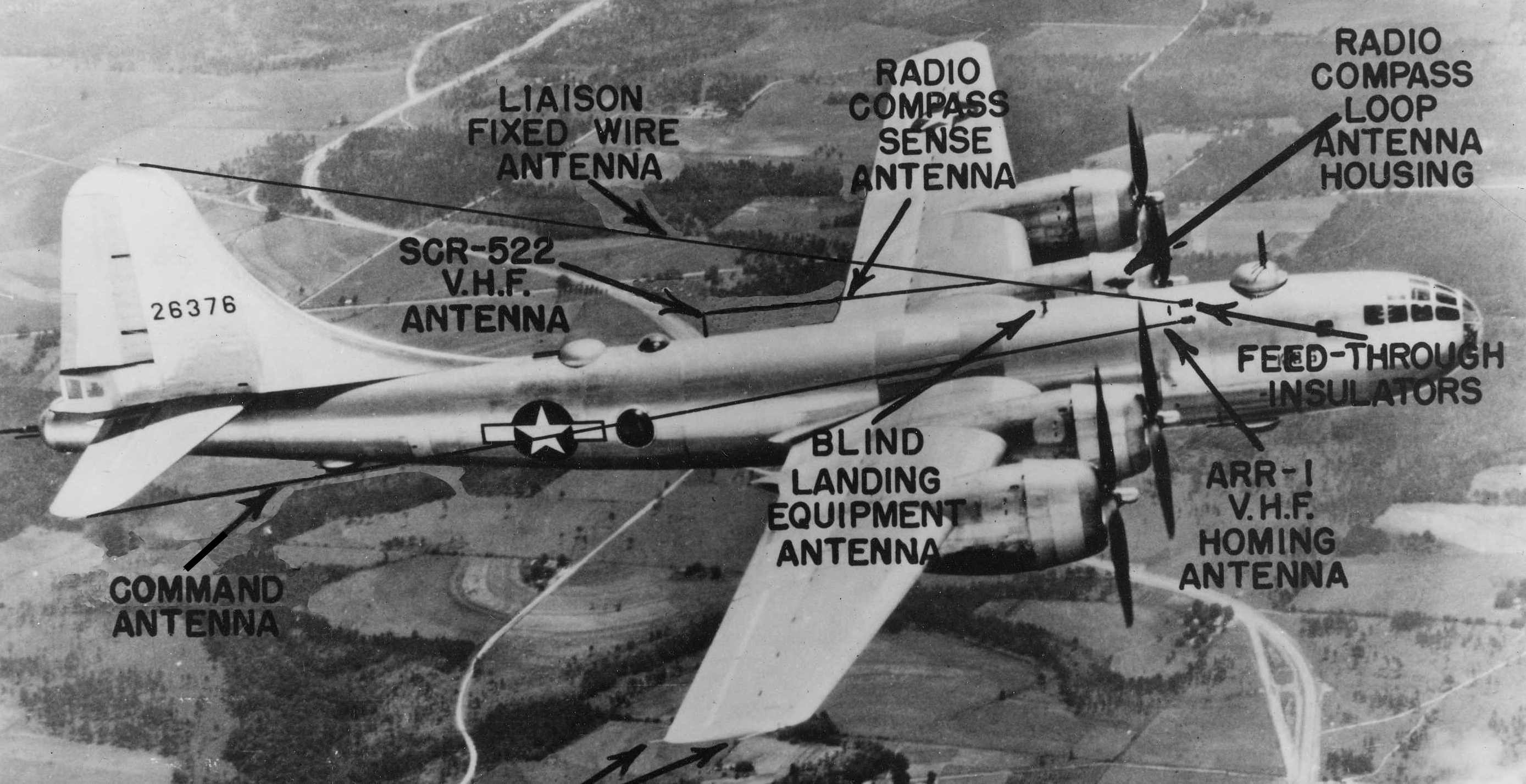
The picture above shows most of the antennas on the exterior of the fuselage. Beginning with the long wire
HF (high frequency) radio antennas, there were two of these, one for liaison and the other for command functions
(See "Radio Operator's Station")
for a description of the difference.) Each was about 75 feet long. The early B-29 command antenna was copied
from B-17 practice, running between the lower insulator shown on the fuselage to a point on the rear of the No. 3
engine nacelle, employing a portion of the wing and fuselage in effect as a large loop antenna. Performance
and tuning effects moved the designers to change the installation to that shown above. Though a normal B-29
also had a "trailing wire" antenna that fed from a point on the fuselage beneath the wing on the right side,
the Silverplate aircraft had this and the MF (Medium Frequency) components for the ART-13 transmitter removed
to save weight.
What is labeled above as the SCR-522 antenna is the VHF (Very High Frequency) communications blade. The forward
"blade" on this earlier aircraft photo is actually a solid mast without antenna connections. In the
Enola Gay, the later AN/ARC-3 was installed in place of the SCR-522, and in fact there were two of these sets
on board - one below the radio operator's feet in the unused lower gun turret and one below the floor in the
waist gunner's area. By this point in the war VHF was used for the command function, rather than the HF
capability. An additional VHF antenna replaced the solid mast on the Enola Gay, and the radio compass sense
antenna was strung between the two blades.
The "sense" antenna works alongside a loop antenna that is located inside a plastic housing that looks like
a football on a pedestal (and was in fact called the "football" by the flight crew.) Use of the loop antenna
alone gave the navigator two possible directions to a radio transmitter, each 180 degrees apart. Addition of
the sense antenna eliminated that ambiguity. A closer picture of the sense antenna is shown below.
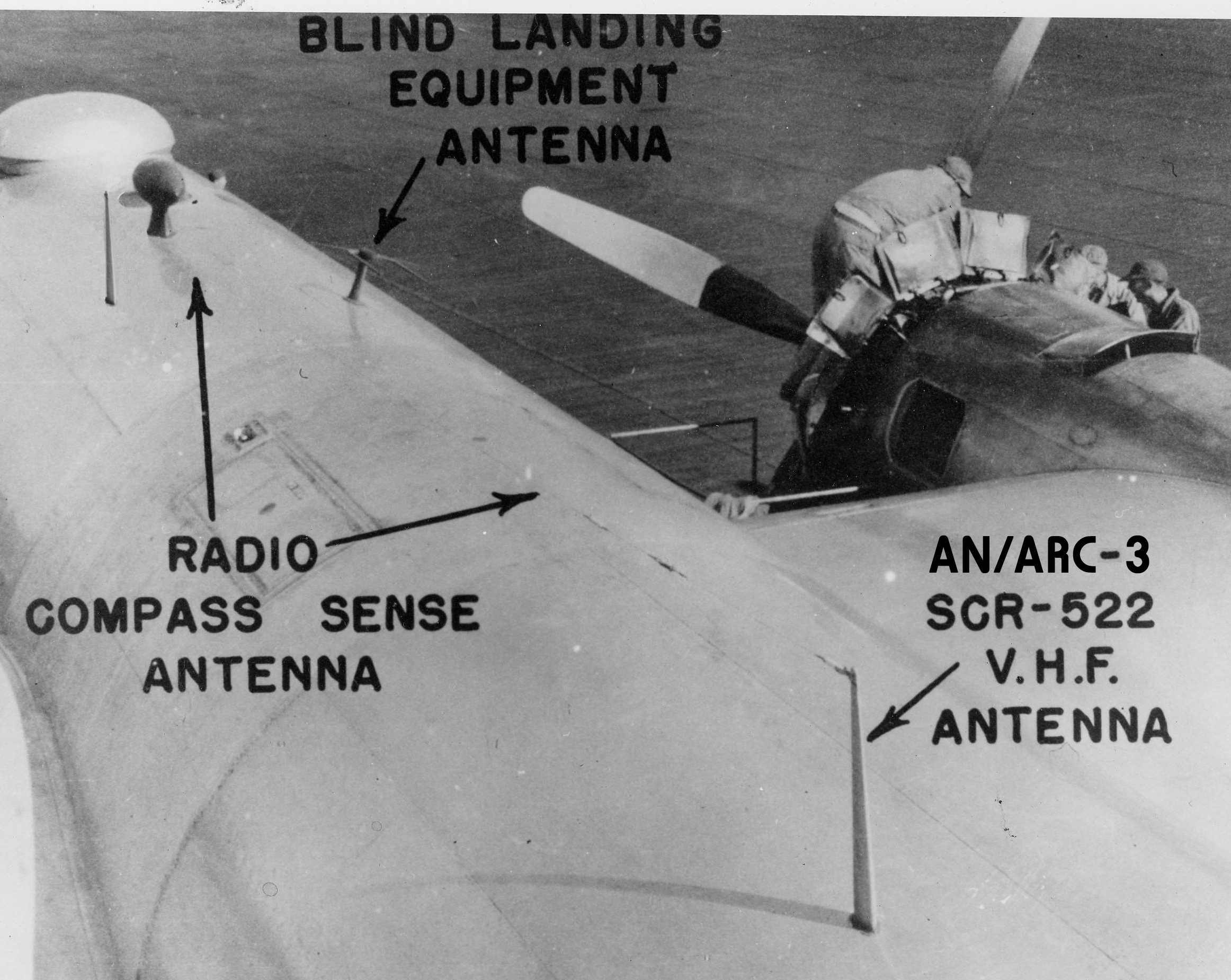 Top side antenna detail
The blind landing equipment antenna seen above and below, looking sort of like a horizontal set of horns
from a Texas longhorn, was a later addition to AAF aircraft in the Pacific. The Navy had long experimented
with blind landing equipment, but the AAF didn't field a capability until a system labeled the RC-103
(and later the AN/ARN-5) became available. The system allowed a pilot to make an approach to an airfield
with a degree of confidence that he could get in sight of the runway. A special indicator in the pilot's
instrument panel
(See "Pilot's Station") with
crossed needles was used to gage whether the plane was above or below and to the left or right of the glide path.
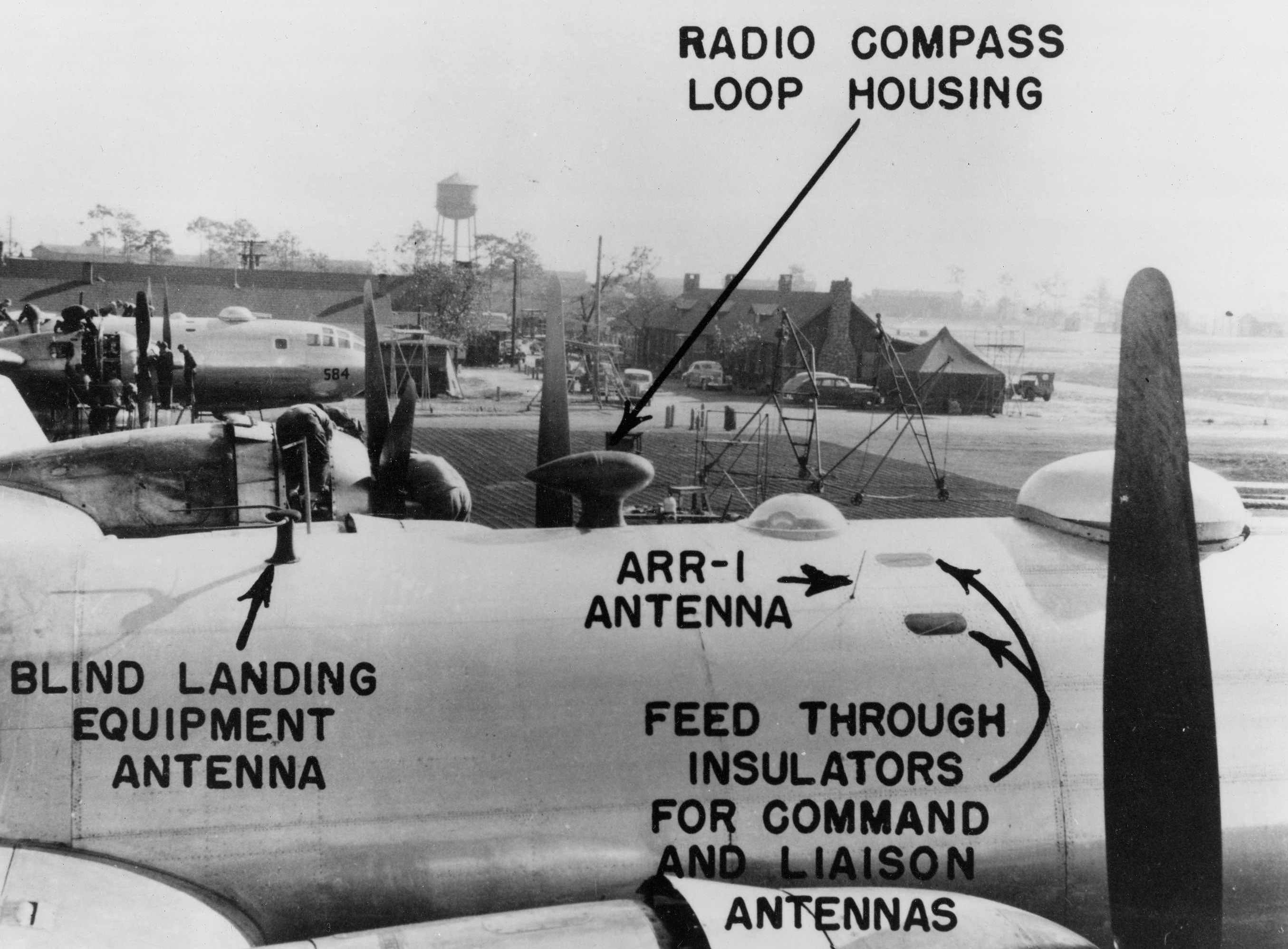 Starboard side antenna detail
The ARR-1 antenna shown above was not actually installed on the Enola Gay. The AN/ARR-1 and its successor
the ARR-2 was a Navy system that was used primarily in the Pacific for aircraft to home on a special radio
signal transmitted by a mobile transmitter. It was used extensively for carrier aircraft because of its
light weight and ease of use in finding a fast moving carrier, and was installed on most B-29s as additional
insurance for the navigator. Since the system was portable, it could also be set up at various airfields for USAAF use.
The clear plastic bubble above the ARR-1 antenna is for the navigator to take sextant and astro compass readings.
The two oval ports described as "feed through insulators" above are present on the Enola Gay, but in
fact were not used by mid-1945. Their use made antenna repairs more time consuming and the need
to solder the wire coming through each of them to a taut antenna wire actually weakened the antenna, so a
design change was made to that shown below. The small wire hole in the black oval insulators was simply
filled with a sealer, rather than replacing them completely with aluminum patches.
 HF antenna feed through detail
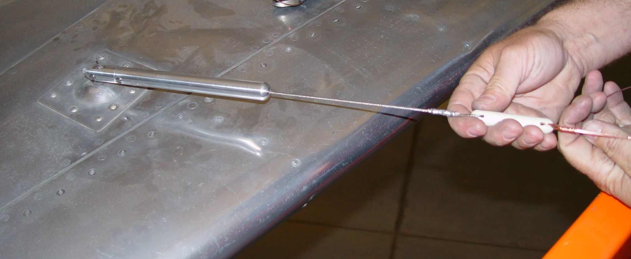
The other end of each of the HF antennas was fastened to a spring-loaded tension unit. The one on the horizontal
stabilizer is shown below. These tension units allowed the antenna wires to adjust to temperatures from 60 below
to 140 above zero without breaking.
 HF antenna tension unit
There is one additional antenna not shown on the photographs above - the one selected by the RCM Officer (Radio
Countermeasures) in the Enola Gay to scan for possible Japanese interference at the bomb fuse frequency.
(See "Electronic Countermeasures Position")
for details.) That antenna is shown below.
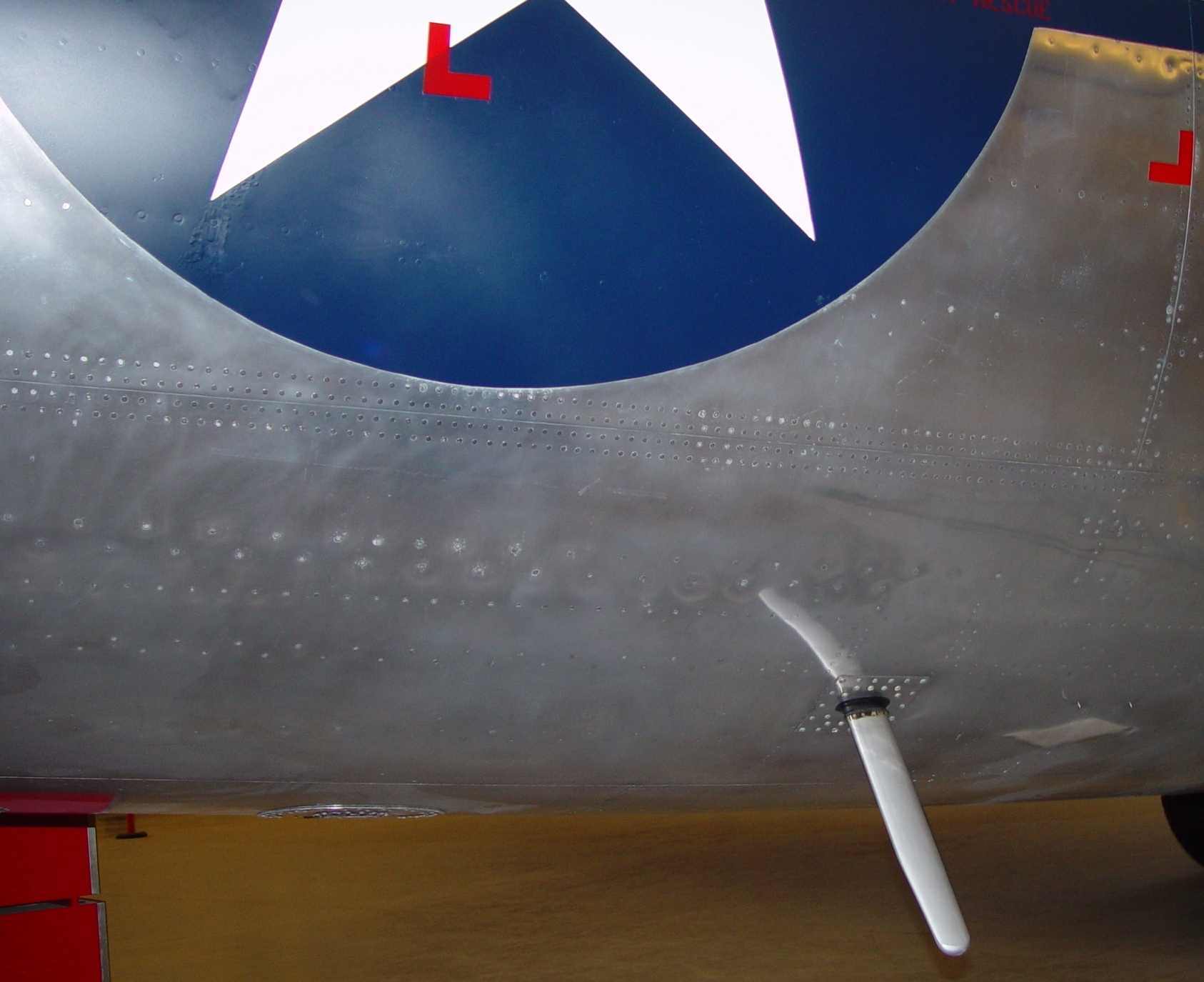 Starboard side countermeasures blade antenna
There are actually half a dozen antenna ports in the skin of the aircraft in this general vicinity. You
can see another port (capped off) at the bottom of the aircraft to the left of the blade. A closeup of
this second port is below.
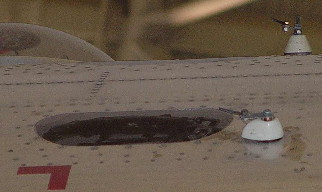
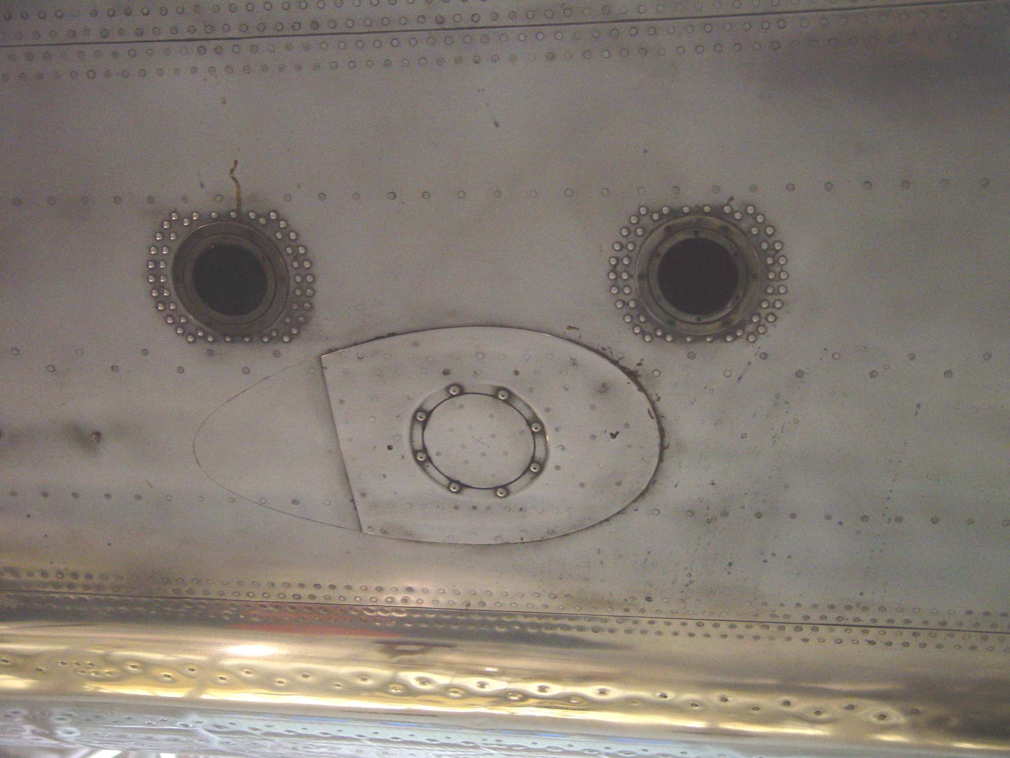 AT-49 antenna port
The port above is shown because it was configured specifically for a certain type of antenna - an AT-49
or similar cone antenna. The reason for pointing it out is that it was the focus of a personal research project
into the specific ELINT antenna used on the Hiroshima mission to determine any Japanese interference on
the weapon fuse frequency. The normal surveillance antenna for this frequency (~415MHz) was the AT-49, a
delicate dome crowned, cone shaped antenna. It required a tear drop shaped plexiglas wind shield to keep it
from buffeting in the slipstream at cruising speeds. In this photo is seen the standard skin reinforcement
installed at the factory to accommodate this wind screen...note the #2 pencil extension of the tear drop that
I put on there temporarily to check for indications of fasteners.
In the Enola Gay, there are no signs of the additionally required holes for rivets or other
retaining devices! That lead to months of searching for photos of the mission and its aftermath, all
without conclusive results. Finally, in a motion picture of the return on August 6th, just a momentary whisper of a
blade antenna is seen on the starboard side of the aircraft - enough to identify it as an APT-4 variant. Of
such small clues are interesting discoveries made...
A fully fitted B-29 in the summer of 1945 would have many of these ports filled with surveillance and
jamming antennas, but the lack of Japanese reaction to flights of two or three aircraft made conventional
electronic countermeasures unnecessary for the atomic missions.
Finally, shown below is a photo of the special instrumentation antenna mentioned in the Electronic
Countermeasures Position. This was primarily intended for use when the aircraft was configured as
the instrumentation plane, but could be used at any time with the ARR-5 VHF receiver in the
countermeasures position.
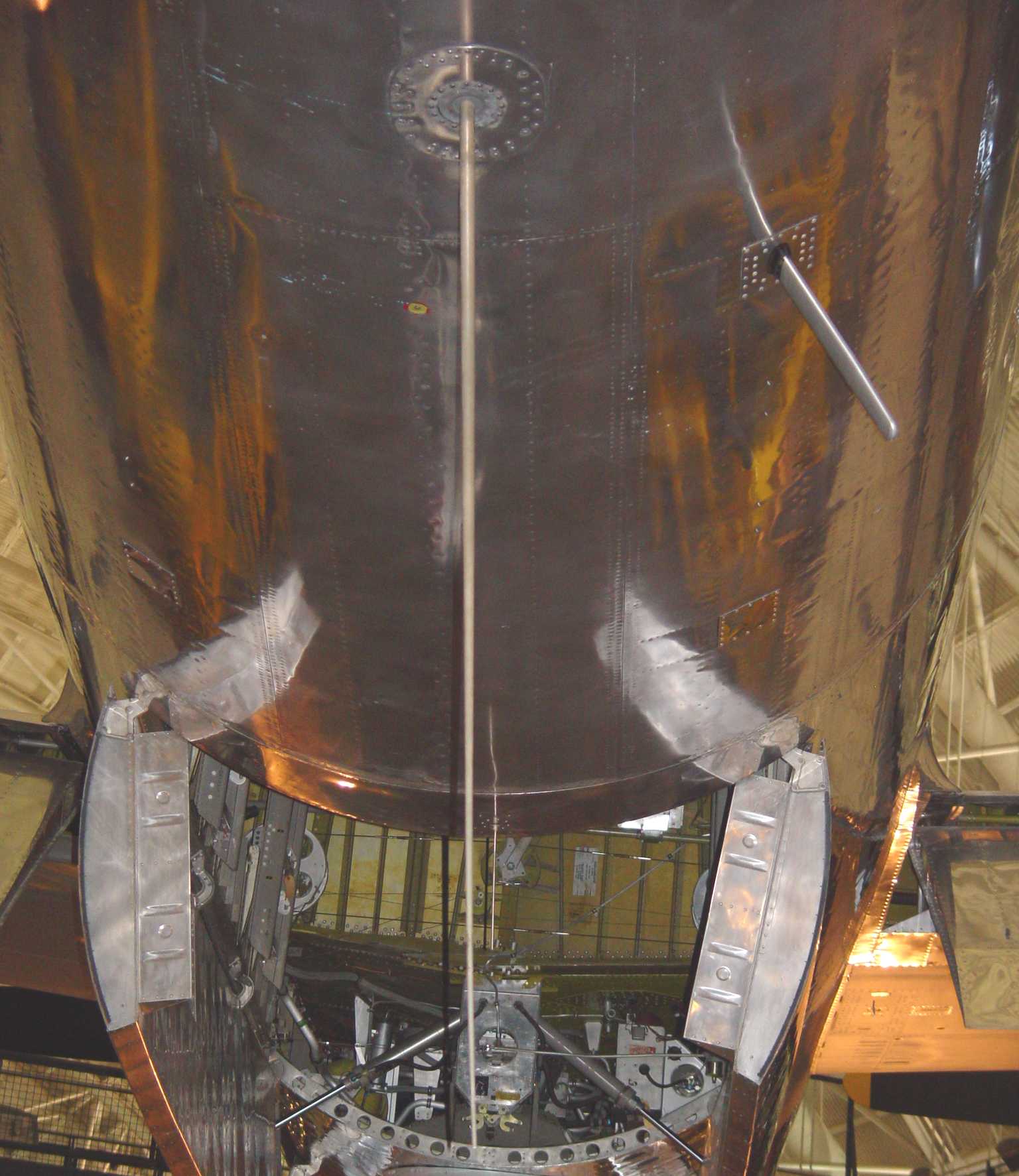 Instrumentation canister antenna deployed through its port. Bomb fuse surveillance blade antenna
is to the right.
Instrumentation canister antenna deployed through its port. Bomb fuse surveillance blade antenna
is to the right.