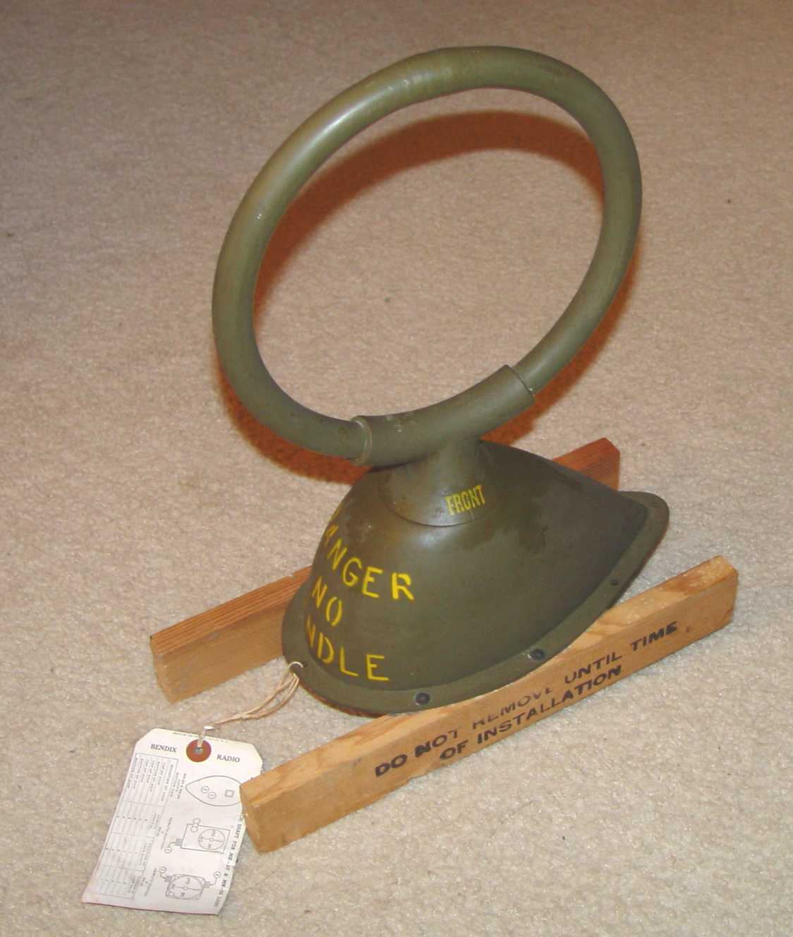
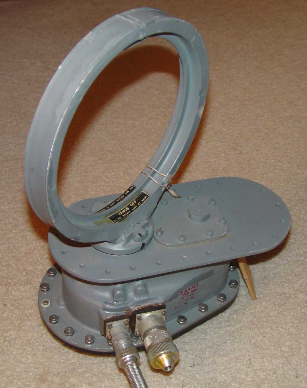
MN-20E loop antenna for MN-26 and RA-10 receivers
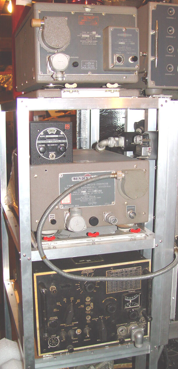
This particular bay was really an afterthought. Until the prospect of amateur work being possible below 500kHz, inclusion of any of the navigation receivers seemed to be inconsistent with the general rule for the fight deck - "Everything should be useful, at least in some fashion." If I keep my weight down to a 96 pound weakling or really "suck it in", just enough room is left in the entry gap into the octagon shaped array of racks to accommodate a vertical column of the most common manual and automatic direction finding receivers used during the war. These receivers were teamed with loop antennas and not only found application as radio range beacon receivers, but also functioned as independent direction finders on signal sources whose position was known, such as AM broadcasting stations. Often the aircraft had both kinds of receivers, one of those depicted here and a MF command receiver such as the R-23/ARC-5 or BC-453 to handle the radio range system. That allowed cross checking bearings (at least where the radio range was established), though in the vast reaches of the Pacific or in forward battle areas of either theater, the larger receiver was often the only one providing any accuracy. The control boxes for these receivers are mounted to the right of the bay and are shown on a different page - Navigation Panel
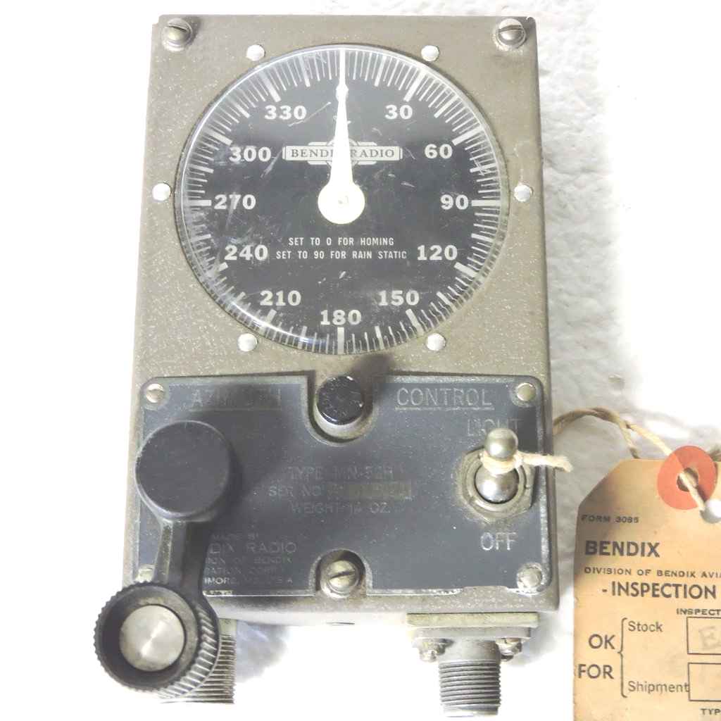
Beginning at the top is a dual purpose receiver, the Bendix RA-10. It actually doubles as both a navigation set and an HF receiver, teamed with the TA-12B transmitter just out of view to its right. The frequency range of this particular set (an RA-10DB) is 150-1,100kHz and 2.0-10.0MHz. Its MN-20E loop antenna is shown below, a manually steered loop that uses the MN-52B Control below it to change azimuth. The complete RA-10DB manual is posted here.
The antennas for these receivers are all rotatable loops, some more complex than others. All of these will eventually be installed near the ceiling of the "flight deck".

Below the RA-10 is another well known nav set, the Bendix MN-26. These receivers came in a surprising number of variations. Though all similar in appearance, different frequency ranges were available for different theaters, leading to a frustating time trying to match the control head with the receiver. This particular one is an MN-26LB, and has bands of 200-410kHz, 550-1,200kHz, and 2.9-6.0MHz. It is the one peculiar version of the MN-26 series that was also officially nomenclatured as the AN/ARN-11. Like the RA-10 receiver, this uses the MN-20E loop antenna shown above. The remote control is the MN-28LB below.
Perched on top is a small ferry beacon receiver, employed with the radio range system in aircraft that needed to be moved from one place to another but had yet to have a radio compliment installed. This was fairly common during the time when the destination of a particular aircraft out of the factory could be either the European or Pacific theaters.
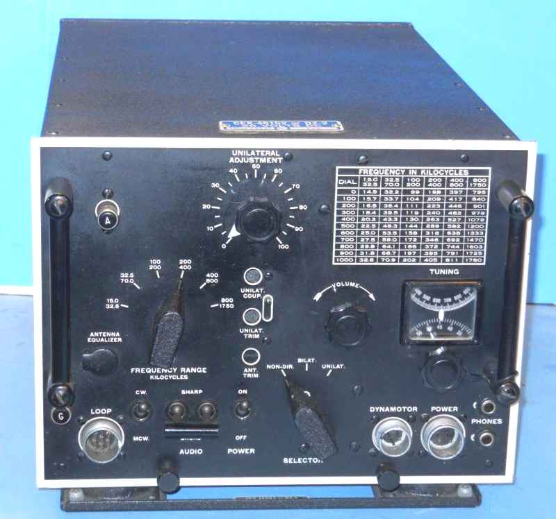
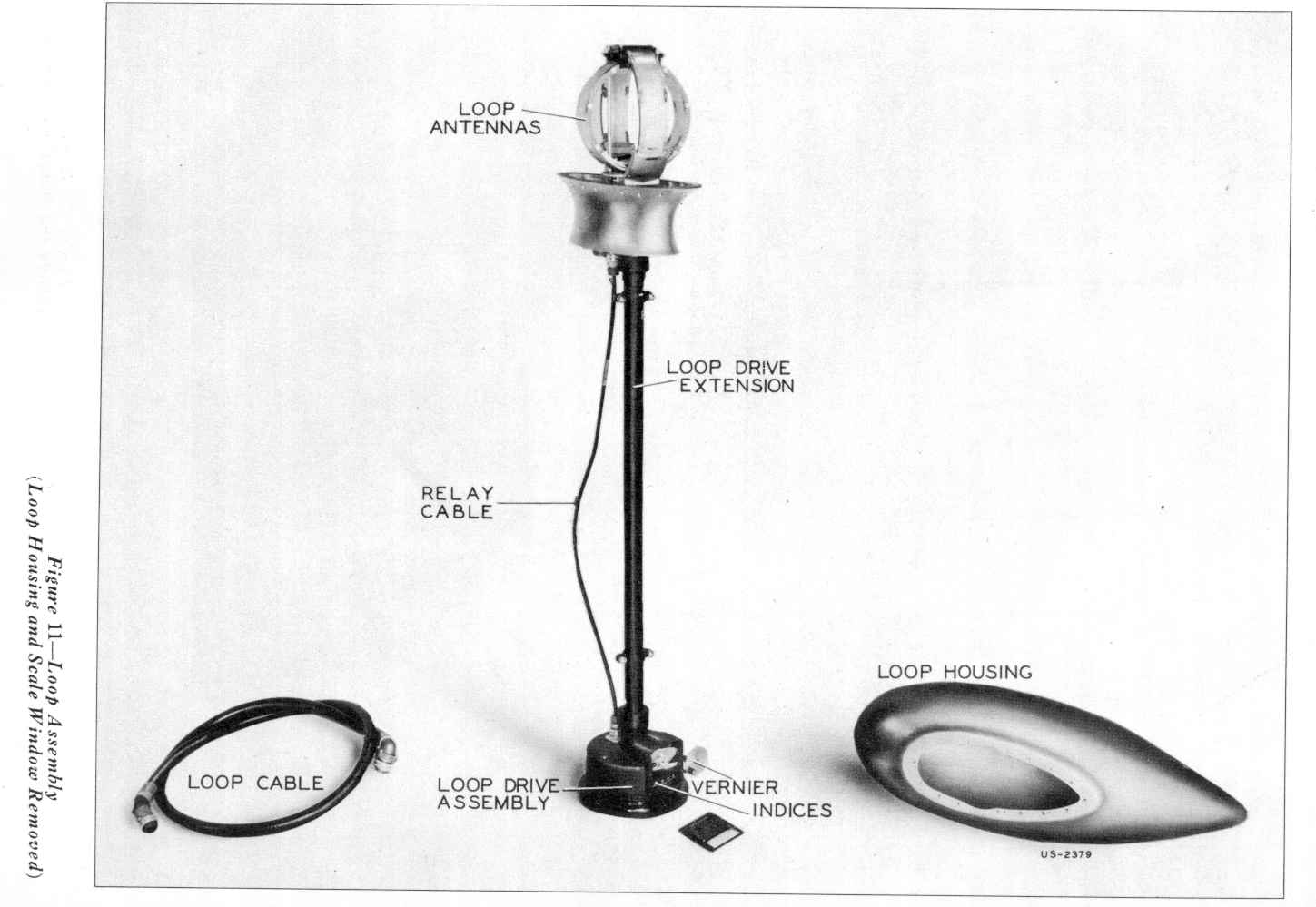
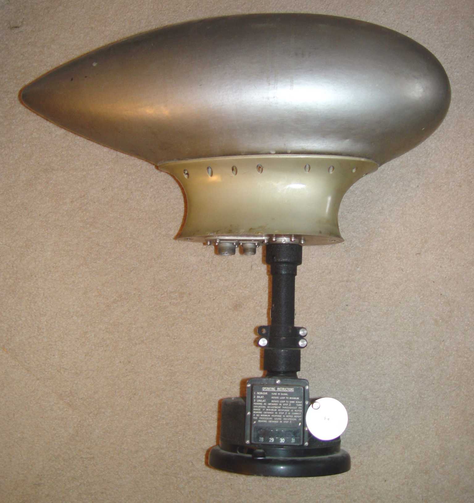
Next in line is the Navy's primary "big gun" DF receiver - the DZ. This is a DZ-2 model, and employs a sophisticated goniometer crossed loop design by RCA. This loop was rotated manually by a knob at the bottom of the loop assembly, limiting its placement within the aircraft to a position near the navigator or radio operator. The frequency coverage of this set is a remarkable 15kHz to 1,750kHz in six bands (15-32.5, 32.5-70, 100-200, 200-400, 400-800, and 800-1750kHz.)
The design of this receiver was essentially from the late 1930s, and that earlier architecture is apparent in the lack of any sort of remote control box for it.
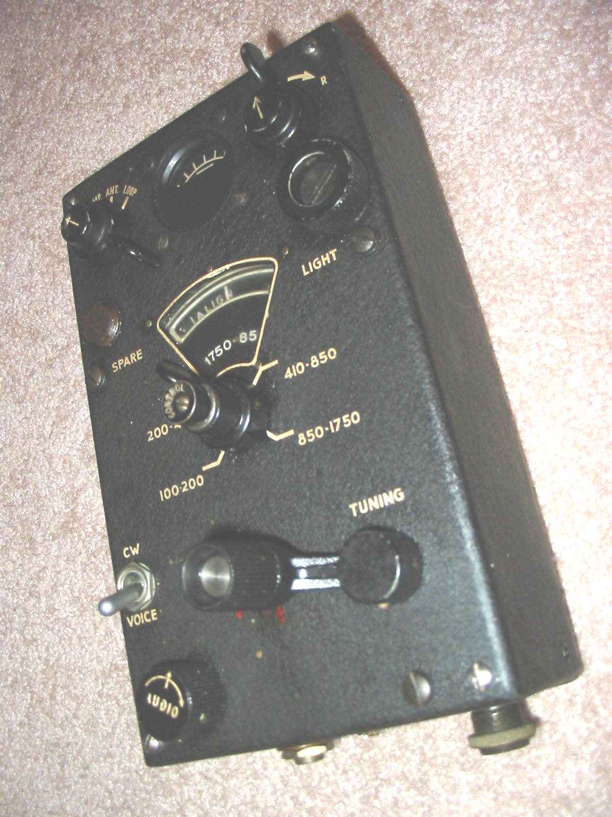
Below that (unseen in this photo) will be what both the Navy and USAAF finally settled on toward the end of the war as the joint DF solution - the AN/ARN-7. An evolution of the Bendix SCR-269 and its predecessors, it offered completely automatic loop slewing when the signal was strong enough. The control box for this set is shown below.
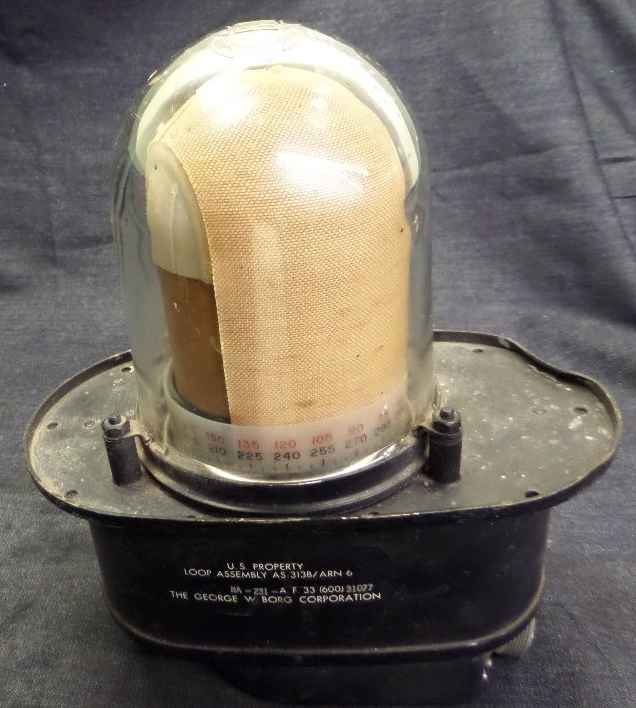
Below the AN/ARN-7 will be mounted an AN/ARN-6, which used a variation of the DZ antenna design to minimize the exposed size of the loop structure. Both the AN/ARN-6 and AN/ARN-7 are automatic DF units, which is to say a frequency could be dialed in on the control box and the antenna slewed automatically until the direction was indicated on a servo controlled indicator.
