B-29 Corner
Perhaps as well known as the command sets is the famous AN/ART-13 and
BC-348 combination used in the B-29. That combination forms the central
focus of this particular corner of the "flight deck" out in the radio shack.
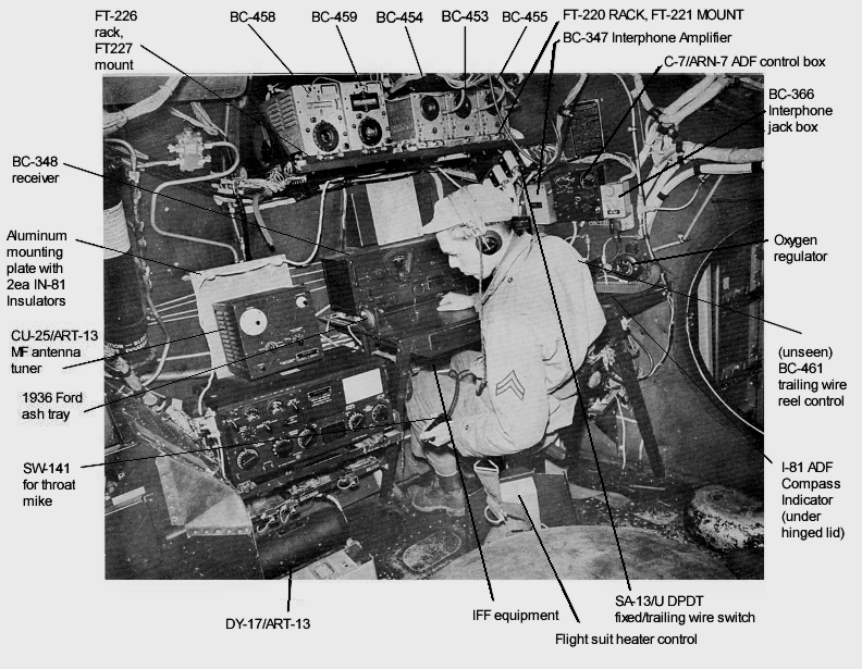
Recent photos of an actual documented installation in a B-29 are shown at the radio operator's station at
Enola Gay crew positions, though it should
be noted that the particular installation shown there was a special configuration for the atomic weapon "Silverplate" aircraft,
and the SCR-274N command set in the picture below was replaced by a second ART-13 at the radio operator's feet. The normal "early"
installation is shown below, marked with equipment designations:
The ART-13 was initially acquired by the Navy from Collins through a contract issued in 1940, and nomenclatured as the ATC, in a
series of airborne transmitters starting with the ATA command transmitter and ending with the ATK
guided weapon television transmitter (this is before the Joint Army/Navy nomenclature system
was invoked.) None of these transmitters had anything in common, as they ranged the gamut of
frequencies and purpose. The ATC simply was third in line when they handed out the designations.
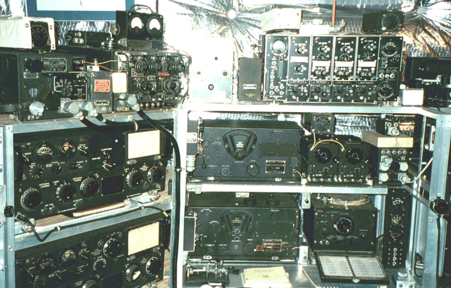
Left to right in the playroom "flight deck" photo above, starting at the top row is the Navy
equivalent of the USAAF's BC-348 HF liason receiver - the ARB with a ZB-3 homing
receiver snapped to its top, followed by an ATB (which RCA designed to
be its "mate"), with an ATB meter box on top. Because the output of the ATB was rather low (about 20 watts),
the reality was that the ARB served more often as a companion to the 100 watt ATC. The ATB usually peformed as a "command" (air to air or air to control tower)
transmitter in the patrol aircraft in which it was most commonly installed. Though not a part of a typical aircraft intallation, the small box in between
the ARB and ATB houses an UNUN (unbalanced/unbalanced) RF transformer to match
the ~5 ohm antenna terminal impedance to 50 ohm coax to get out of my radio shack. More on the mounts for this pair are at
ATB shock mounts
To the right of the ATB is an ATD low frequency antenna tuner and
ATD 100 watt HF transmitter, the
1940 competitor to the ATC. The small box in
between the pair is another UNUN. The ATD contract was awarded in the same month
as the ATC, but was markedly inferior when compared with the ATC. That
second place reputation was earned, not because it is not a fine transmitter
circuit design, but because of operational shortcomings. It had only four
channels as opposed to the ATC's ten, has tiny knobs for adjustments
which are difficult to set with flight gloves, and the plug-in tuning
units were susceptible to the usual problems associated with multiple RF
contacts in a salt air environment, not to mention storage space needs within the aircraft.
Second row: On the left is the Navy ATC with the later shock mounting system - essentially identical to the
later transmitters acquired under the AN/ART-13 contracts. The original shock mounting system was composed simply of
two rigid rails that slid into mating rails similar to the ATD, but it offered no shock absorbing capabilities at all, so was
replaced with the shock mount you see here. An amazingly
enduring design - like the command sets - the ATC was purchased in large quantities for
fleet aircraft use, finding its way into even two place Navy carrier aircraft because
of its 10 channel remote operation capabilities. Next in line to the right is a BC-224-H, one of the 14 volt versions
of the BC-348. The earliest version of the BC-224 was a
BC-224-A
model that started off the entire -224 and -348 series. To the right of the BC-224-H is the
RAT receiver set
and an RL-5 interphone amplifier,
each detailed on other pages.
Third row: A Collins ART-13B is at far left, the last in the ART-13 development series, which has the capability for
crystal control using a CDA-T plug-in module, though this one has a
low frequency VFO module in its place. The -B model also has a switch to extend high frequency operation down to 1.7MHz.
Next in the parade comes the perennial BC-348. This one is a -J model, paired with a special airborne BC-221
frequency meter, known as the TS-164.
Brought about because of the utility the Signal Corps finally
recognized in "built-in" installations of the Navy's LM-** equivalent, it appeared
only fairly late in the war. The TS-164 derived its operating voltages from the
BC-348, was shock mounted to achieve the same visual height as the BC-348, and allowed
much more precise determination of receiver frequency. The small silver boxes
to the right of the BC-224 and BC-348 receivers are CU-92/APN signal
splitters, originally intended to split incoming signals from the HF antenna for
the liaison receiver and APN-9 LORAN-A receiver, but used here with an internal UNUN transformer simply to transition
from open wire to shack distribution coax as close to the receiver antenna terminals as possible. At
the far right is a home-brew metering and power control panel for 14vdc,
28vdc, 115vac 400~, and 115vac 800~ supplies for the equipment on the flight deck.
The view below, rotating to the left, offers a different perspective on the position.
In addition to the equipment described above, to the left of the bottom ART-13B
you can see the Collins autotune receiving mate to that transmitter, the R-105/ARR-15.
It could share the same control box and could therefore synchronize frequencies with
any of the transmitter's autotuned channels, though a separate control box was in fact
available for it. This particular example is a relatively uncommon R-105 receiver from the original ARR-15 contract
in 1945, not the R-105A that appears more often. More on that below.
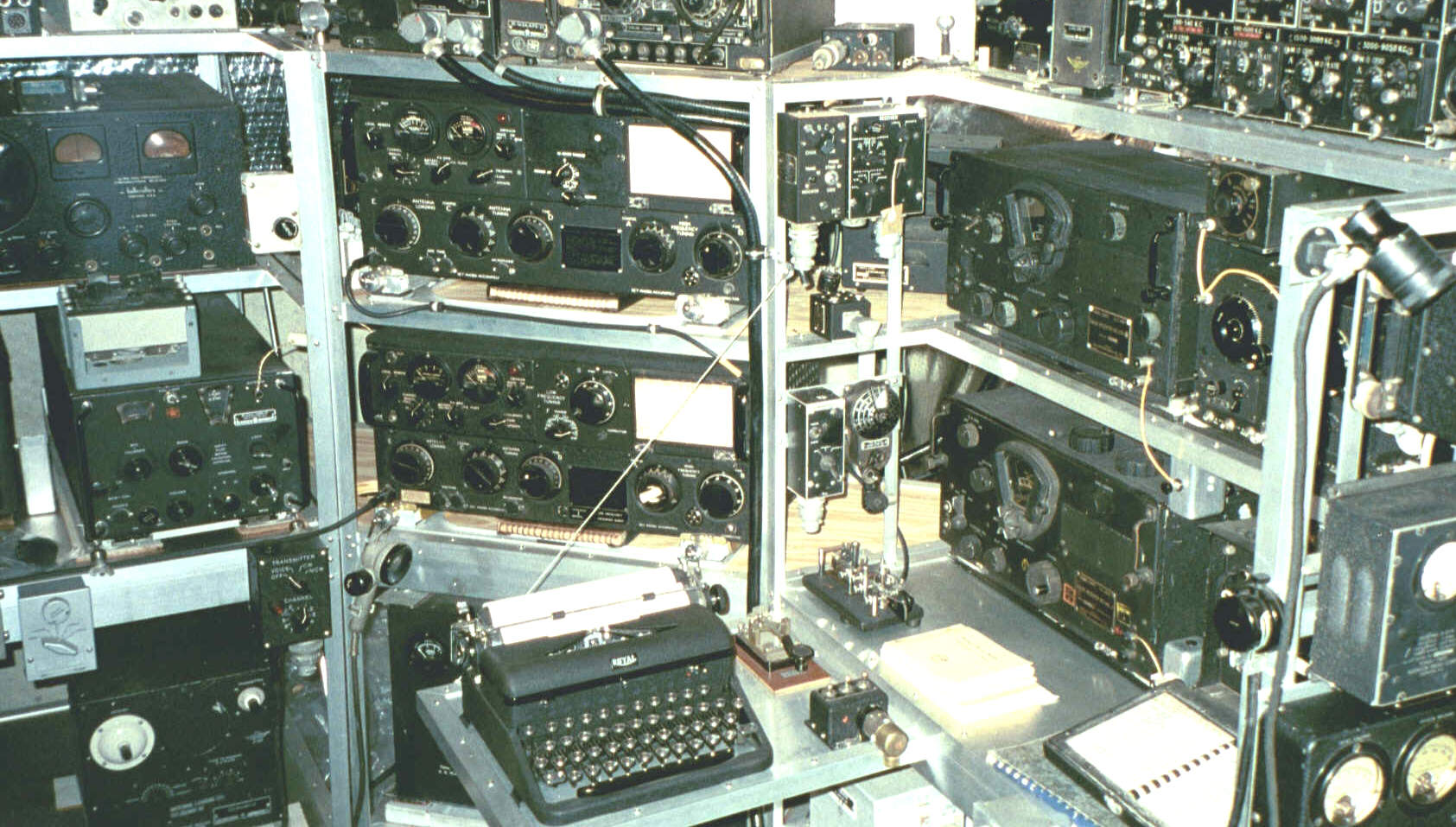
To the right of the upper ATC transmitter are ATD
and ARB control boxes, with an ATD channel indicator box temporarily
stashed beneath until a more useful location makes itself known. To the right of the lower
transmitter are the ATB control box and ARB tuning "coffee grinder".
The typewriter was not a common aircraft radio room accessory, though
anecdotal evidence suggests that many of them were carried aboard. The
keying rate for most of the WWII aircraft transmitters was such that
pencil and paper copy was adequate...as long as the ground end of the
link remembered to reciprocate and send slowly... The hinged shelf construction
with a wire brace is common in a tight aircraft radio compartment.
Below are closeups of some of the Collins designed equipment. The top photo is a closeup of the ART-13
and MT-284/ART-13 shock mount. The shock is needed not only to provide cushioning, but to space the
transmitter up by an inch for its carefully designed convection cooling system to be effective.
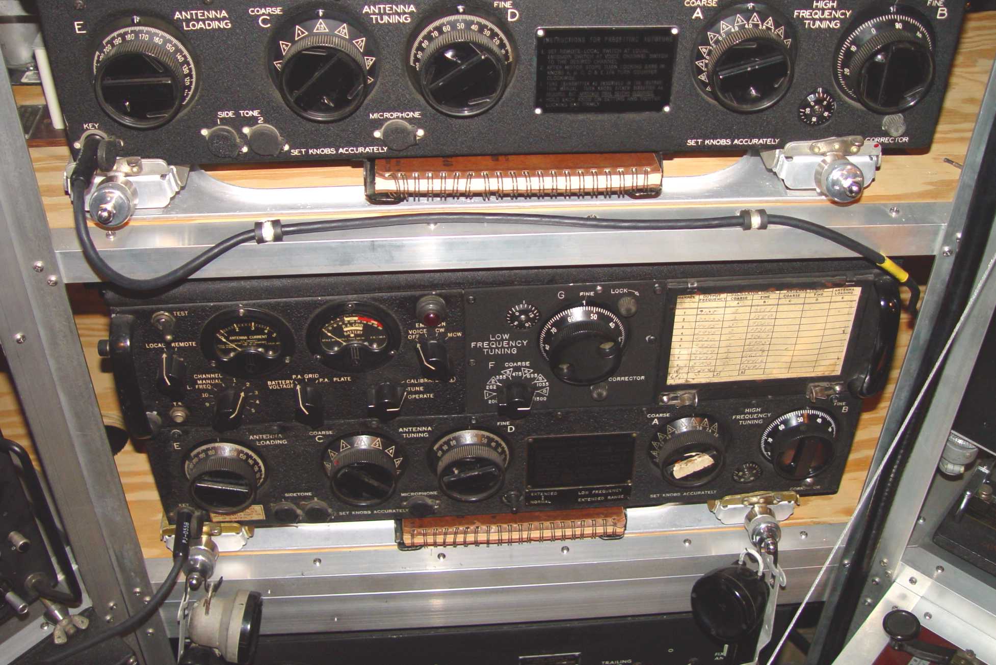 ART-13B Transmitter and MT-284 shock mount details
The next is of the R-105/ARR-15 mentioned above, mounted on an MT-461/ARR-15 shock mount.
It used an unusual variable IF frequency circuit for the BFO and calibration functions.
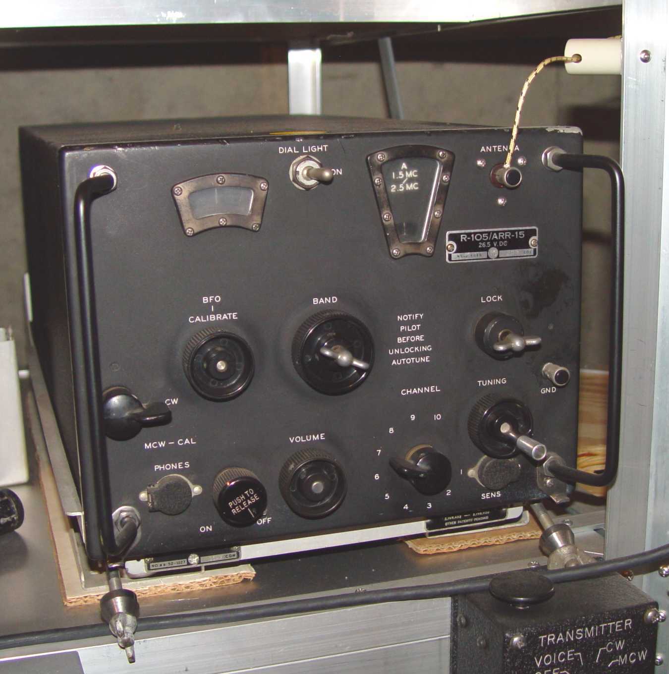 R-105/ARR-15 on its MT-461/ARR-15 shock mount
Below are "The Three Bears", a term I coined because they bring to mind the children's tale of the same name.
They were the MF antenna tuners, and have differing capabilities. The first, the CU-32/ART-13 Papa
Bear (shown on its MT-198/ART-13 shock mount), is actually larger than the transmitter, and contains a vacuum
relay in addition to the usual antenna matching controls. It allowed complete flexibility in connecting the MF
and HF portions of the transmitter into either the trailing wire or fixed antennas, and covered 200kHz to 1,500kHz.
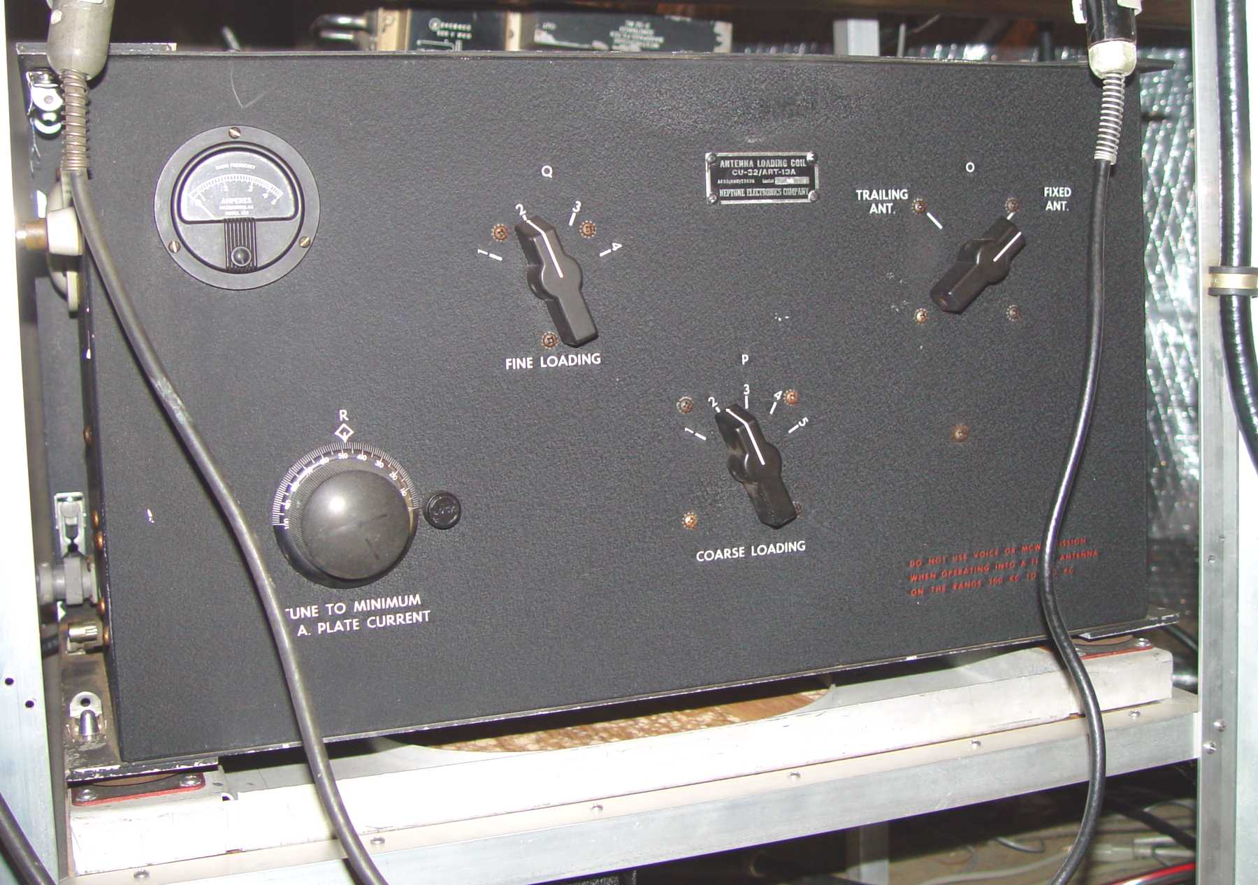 CU-32/ART-13 on its MT-198/ART-13 shock mount
The tuner below is the CU-25/ART-13 "Mama Bear" covering 200kHz to 600kHz, and came in at least three configurations that I can
document. The first version had an antenna current meter mounted in a shock mounted frame (since the
tuner itself had no shock mount to protect the relatively delicate meter.) The second version (shown
here) had a closure plate to block off the meter hole. Evidently the ammeter was found to be too
expensive and not very useful in normal operation. The last version had no meter hole whatsoever.
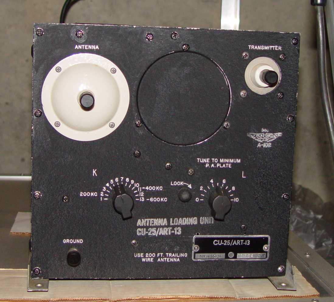 CU-25/ART-13
Last in the series is the CU-26/ART-13 "Baby Bear" below. A minimalist approach to the antenna tuning
problem, it covered only 500-1,500kHz, and would not tune as broad a set of antenna parameters as the
other two. Next to it is the CU-24/ART-13 triple capacitor set used to compensate for highly
capacitive antennas in the 2 to 3 MHz range, and its associated SA-46/ART-13 knife switch for switching
the capacitor bank in and out. Both the CU-25 and CU-26 had earlier Navy ATC equivalents, with the usual Navy five
digit nomenclatures.
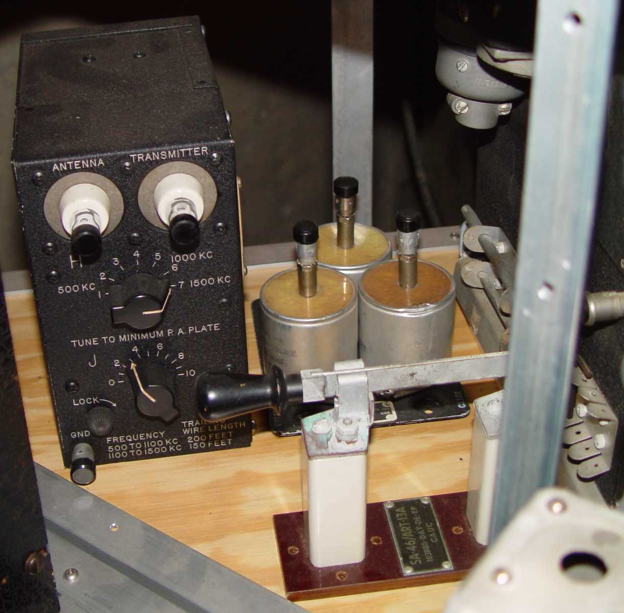 CU-26, CU-24, and SA-46
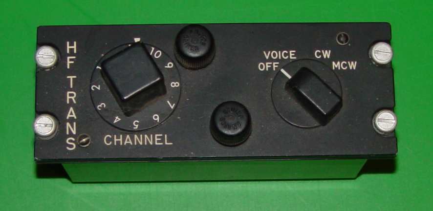
Finally, there were two other peripherals that do not often get mentioned with the ART-13. The earliest
instantiation of a switch to connect the two transmitter outputs (MF and HF) to either the trailing wire antenna or the
fixed (cockpit ceiling to tail) antenna was a simple DPDT knife switch - the SA-13/U. You can see this in the
first photo above of an early B-29 radio operator's position.
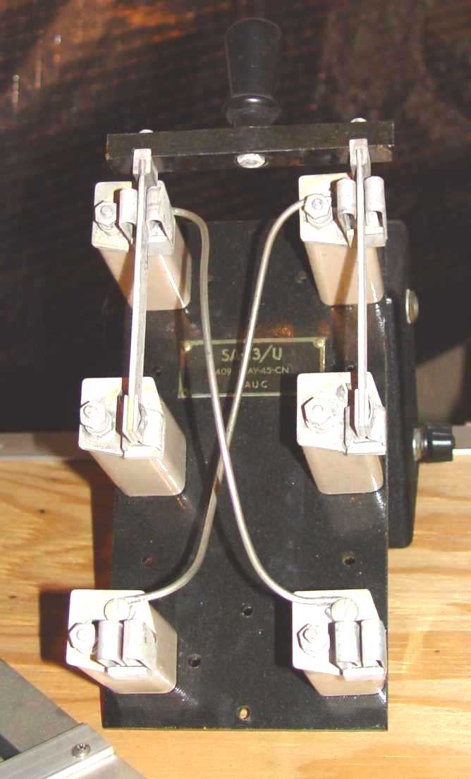 SA-13/U
Tying this into both the MF and HF sections of the ART-13 wasn't very elegant, however, and it exposed some potentially
high RF voltages interestingly close to the radio operator. That situation resulted in
the SA-22/ART-13, shown below for use with the CU-25 and CU-26. The functionality of this switch was
eventually incorporated into the CU-32 "Papa Bear" above. The "PL-259" is an SO-239 output to feed the receiver
antenna terminal, an interesting choice of connectors as none of the liaison receivers of the era used a corresponding
coax input connector, at least in their original form. Some BC-348s have surfaced with an SO-239 adapter box over the antenna terminals,
which may have been prompted by the corresponding SO-239 on the SA-22 and CU-32 (or vice versa). Except for countermeasures receivers like the
AN/ARR-7 and signal splitters like the CU-92/APN, most of the aircraft receivers of the time used the spring clip antenna post
and normal insulated hookup wire for connecting the receiver antennas.
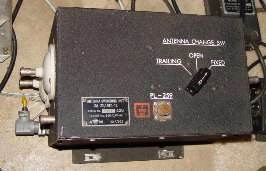
SA-22/ART-13
There were three different remote control heads, ranging from the original surface mount box seen under the ARR-15
(the C-87/ART-13) to miniature rack mounted versions like the interim C-405-A/ART-13 and final C-740/ART-13 configurations, shown below.
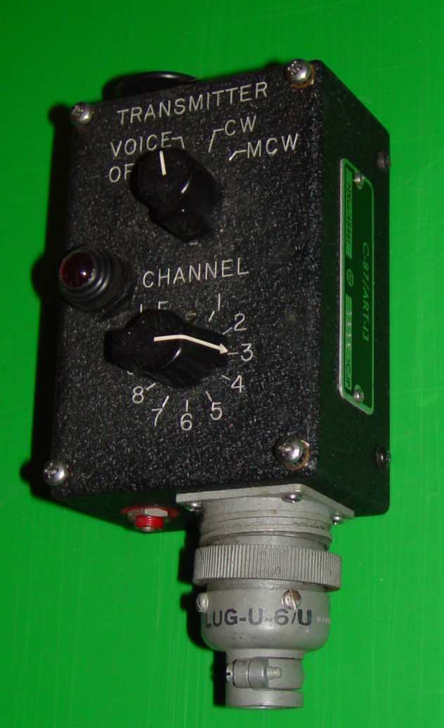 C-87/ART-13
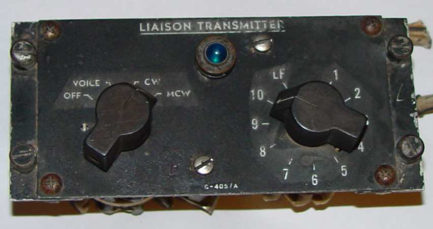 C-405-A/ART-13. This required a multi-wire pigtail that had to be connected to a terminal strip behind the panel,
requiring a certain amount of dexterity and patience. The final C-740 style returned to a standard AN connector.
 C-740/ART-13
No review of this Collins set would be complete without mentioning the somewhat bewildering variations
in dynamotors. There are at least seven dynos I can think of that were associated with the ART-13,
if you include the Navy ATC dynos. The DY-11 and the original DY-17 have "bullet" or
"cone shaped" noses. The original DY-12, DY-12A, and DY-17A have straight end bells. The first photo
below is of a DY-12 , the second a DY-17, and the third a DY17A (this was the last version of the ART-13 dynamotor.)
When the JAN nomenclature system was introduced in 1943 as an attempt to rationalize the confusing mish-mash of naming
conventions among the Armed Services, Navy type ***-21931 was reassigned as a DY-11/ART-13, while Navy type ***-21932 was reassigned as a DY-12/ART-13.
These five digit numbers refer only to the motor/generator portion of the dynamotor, though there were other numbers for the relay box underneath.
The *** refers to the manufacturer's code letters. For example, CWD was the Wincharger Corporation.
The first listing I have for the DY-17A is about 1952, but that doesn't mean the improvements came then.
Functionally they are all identical. The differences were mostly those made by the manufacturer to make
assembly less expensive (punched end bells as opposed to screens and braces, for example) and a change in
fuse holders to more conventional types. They all fit the same mount. The great thing about the DY-17A
is the sealed bearings - you never need to worry about relubing them! Except for fuse and circuit breaker
locations, and a 1/2" step on each side on all except the DY-17A, the base chassis
that the dynos were mounted on is almost identical in either the DY-11, DY-12, DY-17, or DY-17A. The
shape of one dyno end bell is different on the -12, and as I mentioned, the end vents are somewhat
different, but frankly they are nuances appreciated by a very small number of people in the world today.
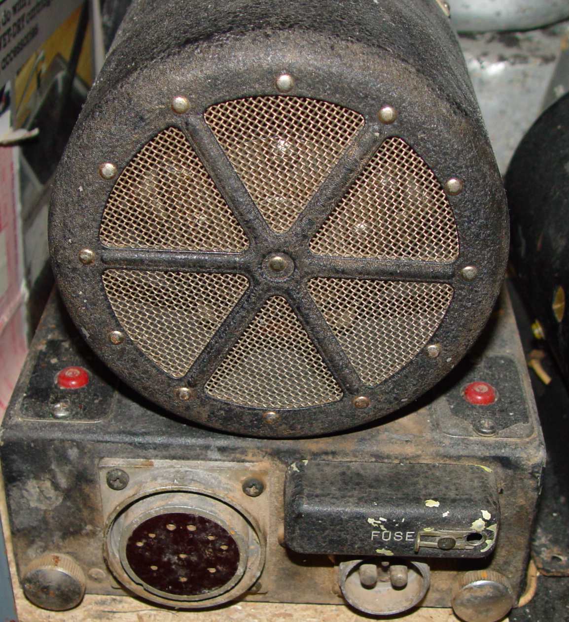 DY-12 end view
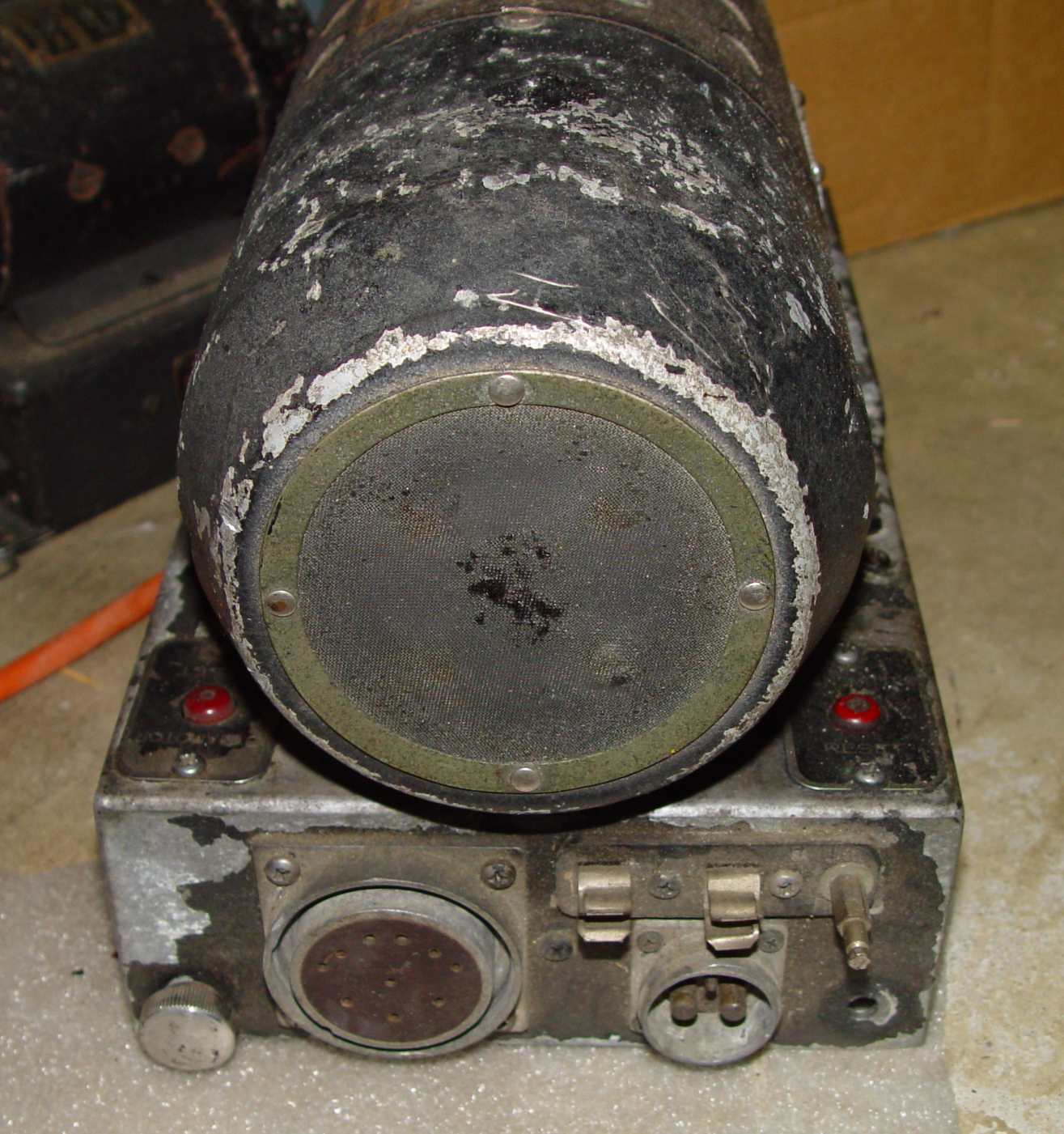 DY-17 end view. Note the cone shaped end bell.
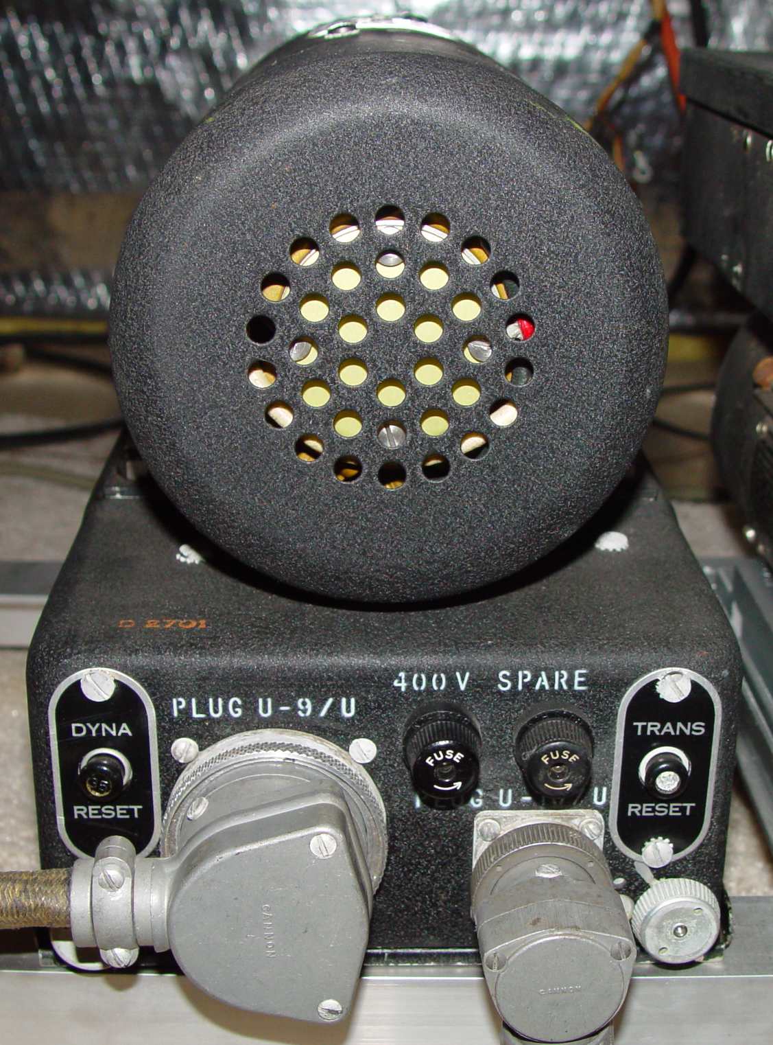 DY-17A end view.
Return to AAFRadio home page