The modulator for this set is an MP-28, shown below, and also contains the dynamotor for powering the transmitter.
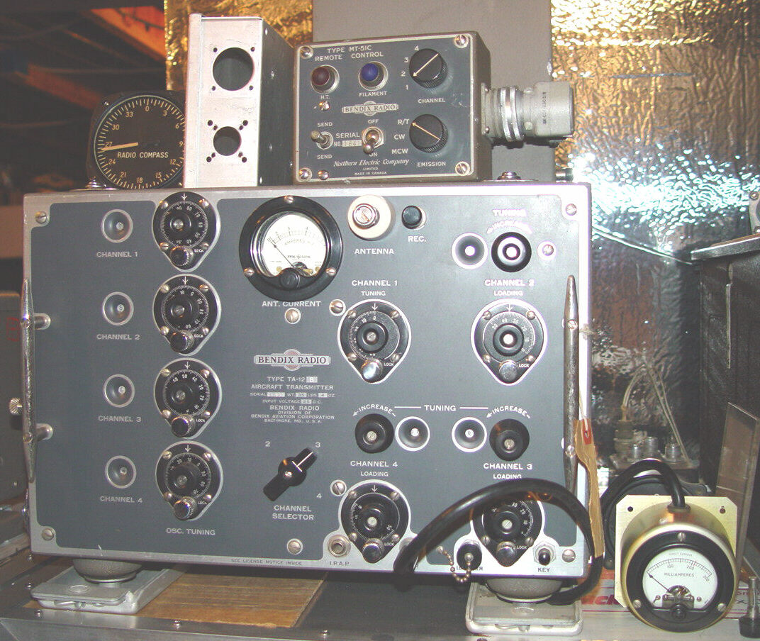
The example below is the TA-12B model, which differs from the more common -C model only by the frequency range. It was primarily used for shorter range HF (and to a degree, MF) comms in light aircraft.
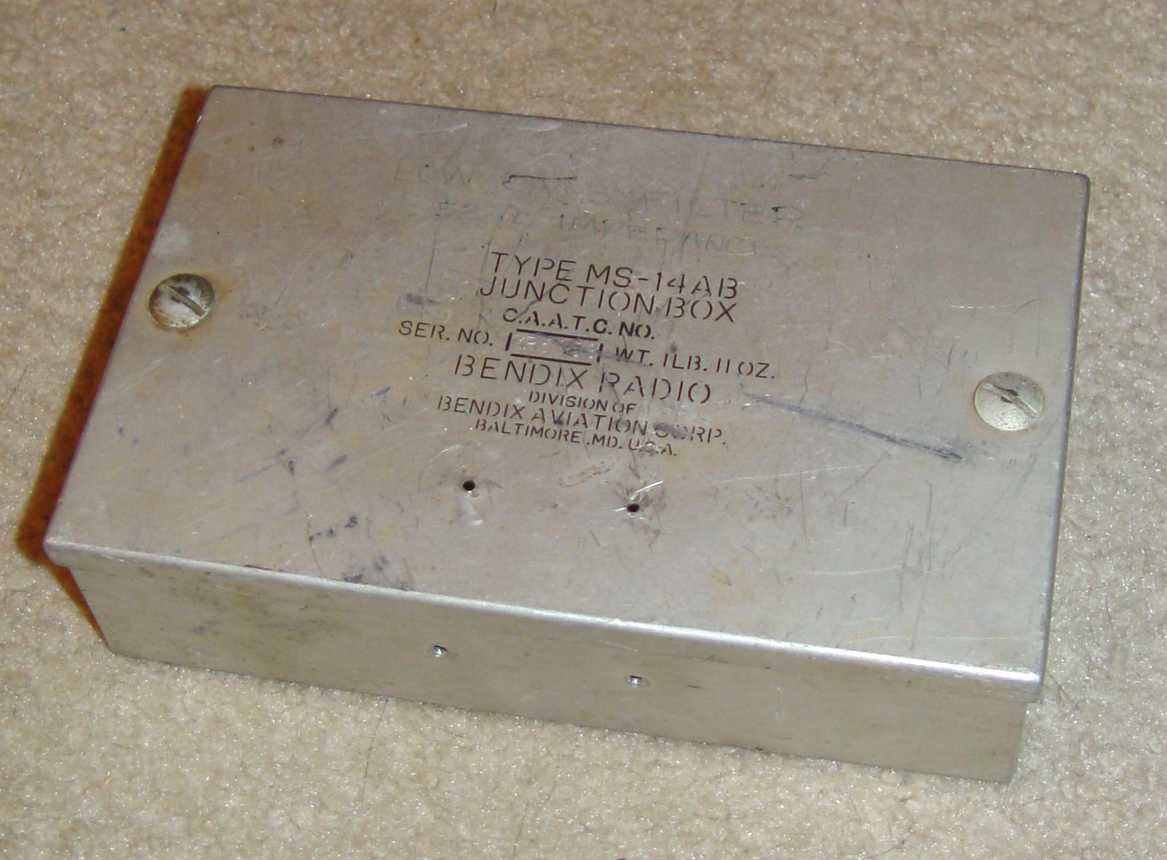
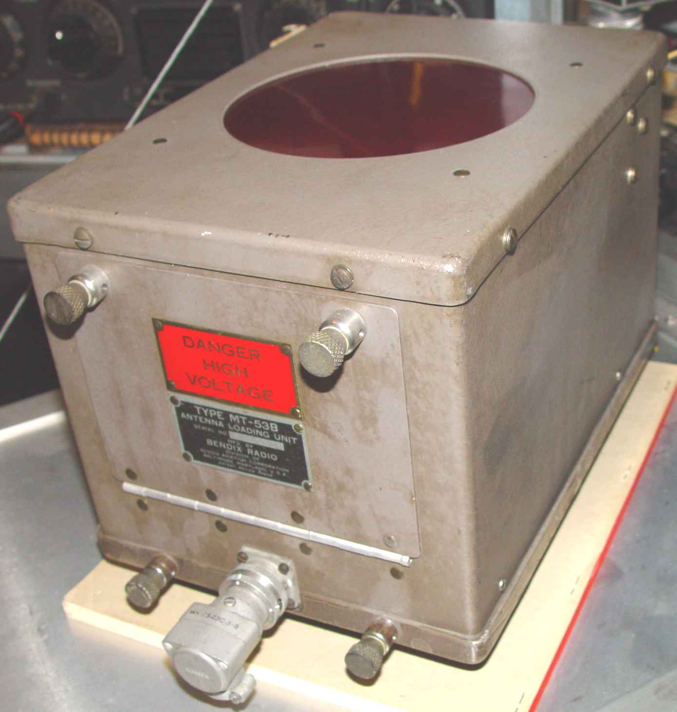
Like the other Bendix eqipment, there is a high piece part count required to put together an entire system. The transmitter above is shown with its MT-51C control box on top and an MT-31C tuning meter at lower right. The MS-14AB junction box is to the left of the MT-51C, and an MT-66A dummy load is partially seen at top right and further down this page. The dummy load is adjusted to simulate the trailing wire antenna of whatever aircraft is being used at the time. (The radio compass is just perched there for scale.) Unseen behind the transmitter is its MP-28BA dynamotor/modulator, and an MT-53B MF antenna tuning coil, but shown below. I need to add another layer to the rack, obviously...

The modulator for this set is an MP-28, shown below, and also contains the dynamotor for powering the transmitter.


The MT-53B antenna tuning coil for MF frequencies is shown below. In the usual confusing manner as most of the Bendix pubs, this is mentioned fairly briefly in the TA-12 manual, referring the technician to the manual for the MT-53B. After running around and spending time trying to find the manual, you are greeted with a very slim document that doesn't tell you very much.

The MT-66A dummy load below was designed for various transmitters in the low power area, like the TA-12. It used a similar sized cabinet as the MF antenna tuning coil above, but substituted a Bendix quick release antenna terminal rather than using the fixed terminals that existed on the TA-12 and MT-53B.

Finally, you have to have something to send morse code, so Bendix produced the MT-11 telegraph key below.
The mating receiver used by the Navy for this transmitter is normally a Bendix RA-10, but that is detailed over on the Navigation page, as it was also used as a DF receiver.