
One of the earliest production superheterodyne command receivers, the 14 volt 1939 Navy RAT, showing the dynamotors for providing 250 volts DC on the rear apron of each receiver.
The development of smaller and smaller DC to DC power converters has finally made the possibility of non-invasive modification of some types of rare receiver dynamotors feasible. This development coincides with a growing consensus that the receivers which they power need to receive a reduced voltage to prolong the life of internal components. The gradual breakdown of components and materials used in building WWII radios is creeping up on the population of NOS and carefully restored examples of these sets, and while a static display is always interesting to hold and examine, there are still many collectors who enjoy experiencing them in a working setting. Conventional approaches usually address replacement of components like capacitors and concealing them inside vintage shells of the original components. This permits operation at original voltages at the expense of "originality". One of the current trends is to drop the high voltage down to levels at which the components can still operate even though there may be some low level current leakage. This approach usually works fine, but has two undesirable side effects. The first is that the high voltage (usually 200-250 volts DC in vintage receivers) is normally required to permit the audio output tube to produce a reasonable amout of audio power. Luckily, this is conveniently solved by using an external audio amplifier. The second effect is operation of the first mixer in a superhetyerodyne receiver, which has been empirically found to begin to degrade in mixer tubes of the era with plate voltages below 55-60 volts DC or so, unless the original voltage divider and AVC chains are modified. Luckily, 60 volts is a low enough plate voltage range that aging components can usually tolerate it and operate satisfactorily (at the moment).
The difficulty of all this fine knowledge then translates to how one could lower the dynamotor voltage, preferably in a variable way, without disturbing originality or requiring expensive workarounds. Traditional options include moving one of the brushes to a different pickoff point around the armature, rewinding the armature, and substitution of armatures from later dynamotors, none of which actually meet the desired goals satisfactorily. They also all leave you with fixed voltage outputs that may need changing again at some point in the future.
Below is an idea I have been toying with for several years, paiently awaiting the technology to enable its execution. Recently, I found some production hardware small enough to fit on a Delrin framework that could serve as a slide-in replacement for the original dynamotor armature. The idea is to simply remove the four brushes and one bearing cage, permitting removal of the original armature, shown below. The static replacement shown below the stock armature would then be slipped into position in the dynamotor, followed by the brushes and the bearing cage. (The positive field wire will also need to have its end taped and tucked out of the way to avoid accidental shorts. Since there is no movement of anything in the modified dynamotor, this doesn't need to be done with the care that motion would normally bring to mind.) This approach is thus easily reversible whenever it was desired to revert back to the original dynamotor configuration. The "virtual armature" shown here is sized for a command receiver, but could obviously be enlarged to fit in (for example) a larger frame dynamotor. Note that the common input/output ground will prevent its use in those receivers whose negative output lead is used for bias, like some models of the BC-348.
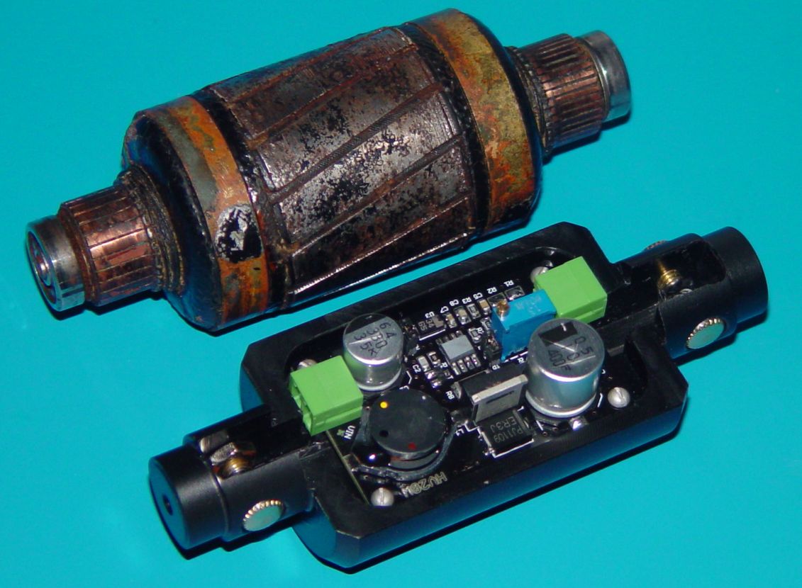
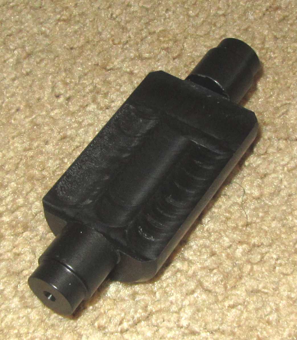
Connections to and from the armature are made with four small contact buttons, installed 180° apart in the Delrin framework where the commutators are normally located on the conventional armature seen above it, and connected back to the converter input and output connectors through channels machined into the Delrin. Subsequent insertion of the original brushes will connect the original dynamotor plug to the converter without any further connections being required. The ends of the Delrin framework are machined to the same size as the OD of the original armature bearings to retain the assembly in the same way the original is held.
While typical receiver dynamotors of the era had power outputs of around 15 watts, the latest versions of these solid state converters are optimised around 12 volt DC and 24 volt DC inputs and have a power output maximum of 20 watts. RF switching noise and temperature rise limits within the enclosed dynamotor are key focus areas for the "armature" at the moment. Current converter efficiency dissipates about 3 watts in the original armature envelope space while supplying a full 15 watt external receiver load, well within normal operating parameters. The dynamotor shell runs cooler than the original, helped by the fact that the field coils do not need to be energized.
Progress updates will be added as development continues. Next steps include measurement of RF noise and regulation over the typical load variation experienced in the WWII receivers. Since the dynamotor frame and end bells form an electrostatic shield, there doesn't seem to be much noise escaping the envelope, based on some quick measurements. I/O lead noise should be fairly easy to reduce if it is a problem. The key will probably be to ground the dyno frame solidly to the receiver chassis, as was found necessary with the normal dynamotors later in the war, due to brush noise.