Dynamotor Restoration
- Michael Hanz - KC4TOS
There must be a little bit of jet pilot wannabe in military radio connoisseurs, because the whine of a dynamotor or inverter spooling up seems to be a cherished thread. Although my main interest is airborne ECM equipment of WWII, somehow I’ve ended up saddled with everyone’s dynamotor problems - probably due to a misspent youth building big block Chevy drag racing engines. (...please note I didn’t say I did anything as foolish as driving them...) Fortunately, restoring dynamotors isn’t as demanding or complex, but it does take some of the same thought and attention to detail. The techniques also apply to the 14/28 volt motors used for cooling fans, autotune mechanisms, and the like.
Caveats: This is not intended to be a step by step procedure, nor replace a maintenance manual. There are so many variations, special cases, and measurements needed that a manual for the associated equipment is essential. Get one and use it. Neither is this a tutorial on theory and nomenclature of dynamotor parts. You can get that out of a manual, too. The intent of this article is to fill in some of the unstated procedures, how to avoid "uh-ohs" - things you do because of hard experience, but generally not recorded anywhere. You can use as many or as few of the ideas as you want - there are no absolutes in this business.
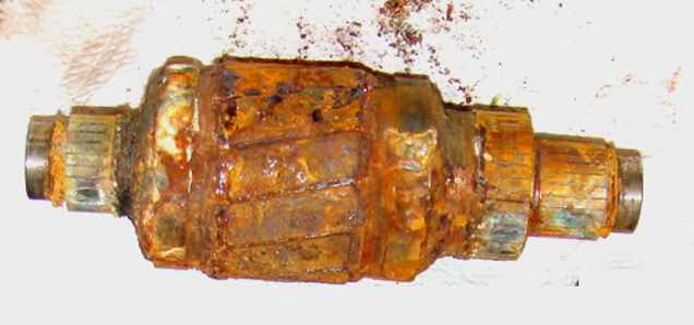
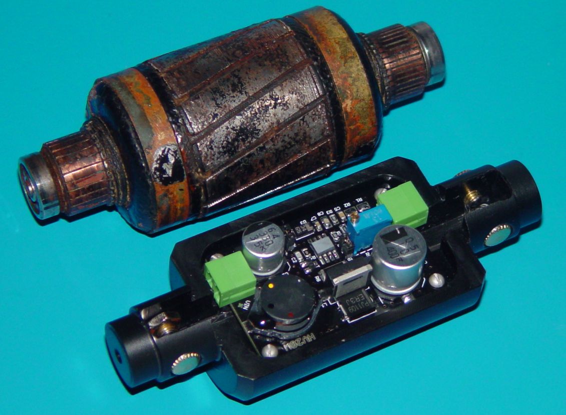
The most common question I get is, "Do I need to take a motor apart if it appears to be clean and undamaged?" I’ll just summarize by saying that it’s dangerous to run up an old motor, even a "New In the Box" unit, until you’ve at least checked the brushes, and cleaned and repacked the bearings - it can save a lot of heartache later on. Seventy five year old grease loses its ability to "float" the bearing surfaces on a film due to evaporation of the lighter components, and the result is a wiped bearing, sooner than later. If you "just gotta"; test it, then at least put three or four drops of a good lubricant in each bearing - I use Mobil I - and don't expect it to last for a thousand hours of running. Then for goodness sake, don't put the end bells back on for testing. The "before" photo of the armature above was the result of a phenomenon called "breathing", where enclosed dynamotors actually breath in and out because of temperature changes over a 24 hour period. Humid air enters the dyno and condenses out on the interior parts, eventually causing what you see above if it goes on long enough. It's why you need to also clean any moisture off of everything in the interior and either throw it into an oven for 24-48 hours at 150°F or so, or operate it for several hours with no load and the end bells off to dry out the interior. Assuming you are going to use the dyno in a conditioned space, you can put the end bells back on after that procedure. I personally just leave them off for operational machines - many motors in the Navy had exposed armatures, and as long as your air is clean, it keeps things cooler and help get rid of carbon dust from the brushes. If your dyno has a fan, then you don't need to worry about the end bells - you can leave them on. If you think you might want to do any more than just test the dynamotor, read on.
Disassembly: The photo above is a good example of your worst nightmare, at least in terms of dynamotors. It also had a case of die casting rot, severe iron oxide disease, and had obviously endured some severe moisture conditions. The good news is that even this can be brought back to at least blue collar working order most of the time. The first problem you might encounter will be recalcitrant end bells (the thin sheet metal covers over the dynamotor ends). A metal oil filter strap wrench will generally remove them without collapsing the thin metal - a little shock therapy on the strap wrench handle might be needed in the worst cases where the joint is badly corroded. Avoid the nylon webbing type - it’ll collapse the metal where the strap gets rolled up on the bar.
Make some sketches or take some digital photos as you take it apart, if you’re not sure you can remember what went where. A copy of the exploded view (if there is one) out of your manual can serve to organize your notes. This is especially important for any clearance adjusting parts, like shims. If you don’t need to replace the brushes or turn down the commutators, then tag the location (and orientation) of the brushes so you can eventually get them back into the same holders they came out of, facing the same direction. This is important! Some brushes hit the armature at an angle, and if you get them in backward, there’ll be one whole lot of wear in a hurry. You’ll probably have to desolder some connecting wires if there’s a plug-in base (as on the command set dynamotors,) or a junction box (as on the BC-375). Don’t forget the wiring color codes!
I generally strip out everything except the pole pieces and stator coils. They’re low voltage, so any small current leakage there isn’t a big problem. If the case and pole pieces are badly rusted, I’ll break loose the staked flat head screws holding them and remove them as well, but it often isn’t necessary. Staking is a process of using a chisel shaped die to deform the screw heads and mating surface so they won’t loosen (in the days before thread locking epoxies). I use a tight fitting screwdriver blade on an impact driver with a hammer to save the screws for reuse. You can chew them out with a chisel, but there’s no substitute for impact (or a long lever bar) when it comes to breaking a bolt loose. Be aware that with a long lever, the screwdriver head will want to cam out of the slot, so quite a bit of pressure is needed to prevent this.
Removing the metal label is usually traumatic - screws are rarely used. More often, those accursed little drive screws looking like rivets with a spiral thread are pressed in. Removing them involves either drilling them out with a machinist’s #1 center drill or, if you’re lucky and their holes go all the way through to the inside, using a tiny pin punch fragment or short nail to drive them out from the inside. A heavy metal bar and needle nose pliers work best with the "short" punch. Occasionally I have been very lucky and been able to grab the top of the pin with small vise-grips and back them out from the top. You can also try tapping a wedge under the label to lift the pin out, but I’ve only rarely had that work successfully - it almost always bends or destroys the label. I normally drill and tap the holes for either 2-56 or 3-48 screws (anticipating the "next" time...).
There’s no shortcut for what follows - a combination of elbow grease, rust dissolvers/ consolidators (try the Rustoleum rust removal kit if you have no other favorite), metal etching solution (Sherwin-Williams W4K 263 Dual Etch works for me), and soap based cleaners. You have to use some judgement in applying the chemicals. I’m particularly careful with the armature, because it has the high voltage winding on it - as much as 1,500 volts! I try to limit its cleaning to mild soap and water. Anything liquid you allow to get in there has to be carefully dried out, preferably by baking for a day or so at 175o. Blow the water out of the rest of the parts with an air hose.
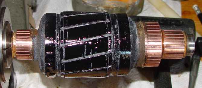
It's fairly amazing what some cleaning can do for these armatures...see Disaster Zone for an extreme example. Note that hipotting of the commutator is essential when you do this much work on it, and generally a good idea in any case.
Check to see how far the brushes have worn into the commutators. If the groove is more than a few thousandths of an inch deep, or has an odd profile, you may need to turn the commutator down in a lathe. Send an e-mail if you want to know more about that - the commutator mica insulators have to be undercut after turning and it’s sort of involved. Most of the manual sections on dynamotors discuss this procedure in more or less detail. Otherwise, some 400 grit wet/dry sandpaper (use it dry) should restore the surface to working order. The standard TM caution about not using emery cloth comes from the fact that this type of abrasive is conductive and will work itself into the most amazing places in the commutator!
Also refer to the TM for your radio to check the length of the brushes - there is usually a specification for minimum length and every doggone type seems to be different. Use a 1/4 inch minimum if you can’t find the spec anywhere. If the die cast bearing/brush cages (spiders) on the ends are crumbling, you have two choices - find a replacement from a junker or try to consolidate the damage with a filled epoxy. I use Devcon aluminum epoxy putty because you can subsequently machine it, but some form of plastic steel might also work. Seal the finished cage with polyurethane, especially if you’ll be operating the motor in spaces like your non-air conditioned garage. If you pulled the pole pieces because of rust, re-lacquer them with a clear lacquer or polyurethane before reinstalling them. This goes for the armature as well (don’t forget to mask the commutators). This is the usually the point at which I put on Nitrile gloves or those little finger stalls. You don’t want to get finger oils on the commutators or clean bearings.
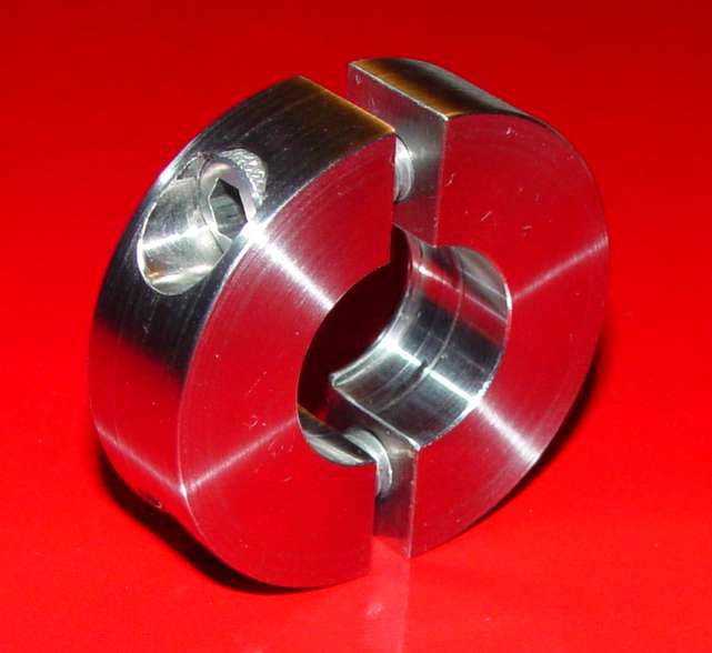
Bearings: This is the single most frustrating but perhaps most critical part of the motor. Some of these armatures turn up as high as 14,000 rpm in normal operation, so you can’t leave this to a lick and a promise. The late and post WWII motors were more likely to have the higher (and more wear producing) speeds, especially the inverters. There are two ways to remove the bearings - one is with a pair of small screwdrivers used as wedges. This method is one of the few ways that the command receiver (DM-32, DY-2) type bearings can be removed - there simply isn't much space between the commutator and bearing to get puller teeth into. I've used a couple of tiny machinist's wedges, but jeweler's screwdrivers will work about as well. You have to be extremely cautious not to nick the commutator or shaft - a task that needs about six hands and five eyes! The commutator is made out of soft copper segments insulated with delicate mica strips, so it’s easier to damage than the shaft. Be careful! A better option if you know someone with a lathe is to make a split clamp like the one I made below for the command set size dynamotors and use a standard bearing puller. It has a thin lip on the rear to fit into the narrow gap.
The second way (if there's enough clearance behind the bearing) is the more standard approach, with a small two arm bearing puller - Sears has a good one (they call it a battery post puller) but I had to grind the jaws on mine a bit to slip behind most of the bearings used on the larger dynamotors. You also have to remove the little cylinder on the tip and file the tip down to a point with an electric drill, or it won’t clear the bearings coming off the shaft. A cheaper (and therefore lighter construction) battery post puller might be better. If that doesn't work with a reasonable amount of pressure, then as a last resort you can to wrap a towel around the commutator, have someone continually wetting it down, and torch the outer end of the bearing with the puller exerting pressure on it all the while. Never had that fail, but it's ugly. Watch out for fire! There’s flammable grease in that bearing.
If the bearings are sealed, factory greased types, there’s not much more you can do with them. If they are still good, it is possible to remove one shield to clean and pack them just like a standard bearing, but then you lose the advantage of its sealed nature. If they are the open type, clean them in a good degreaser, and blow them out with an air hose. Wear safety glasses! The air hose, or a can of compressed air, is essential. I do this at least three times...four if I get any old grease still coming out the third time on the white cloth or paper towel I hold them in.. Check them by spinning by hand, not with the air hose, and listen and feel for roughness. The cautions in the books against spinning a clean bearing with an air hose are aimed at high speed spinning, not hand turning speeds. If you have to replace them, most good bearing houses still stock bearings that will fit the application, though you may have to wade through a few catalogs to find them. You’ll need the outer diameter, shaft dimension, and thickness measured with a dial caliper or micrometer, as well as the working speed.
Reassembly and Painting
As far as lubrication goes, the old greases called out in the TMs were never that good for longevity or lubricity. Do not use wheel bearing grease - it is formulated for much higher radial load, slow speed (~500-1,000 rpm) bearings, and won't cut it over time at 8,000 rpm. For years I've used a synthetic based product by Mobil that is designed specifically for high speed electric motor bearings, called Mobilith SHC 100. But lately I have been using another Mobil synthetic that has a more "spage age" thickener. If you want to use the latest and greatest, get a tube of Mobil SHC Polyrex 102 EM and try it. It will set you back a bit more than the SHC 100, but for those constantly pursuing perfection, you may appreciate the latest Polyurea thickener technology used in its formulation.
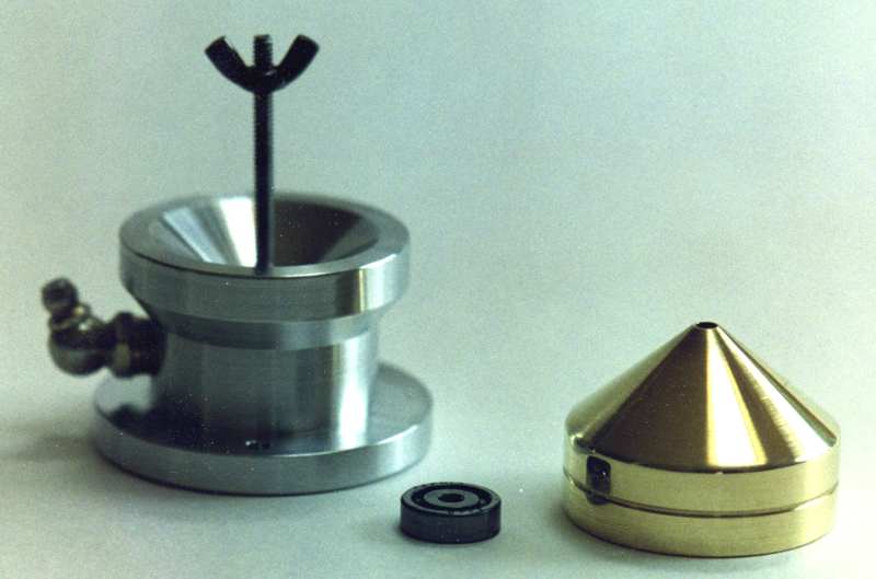
The grease is only half the story. You have to get it into the clean bearing. I’ve tried hand-packing bearings every which way from Sunday, and there are spaces that always seem to resist efforts to force the grease into. It takes a thumb rolling/wiping technique and a lot of patience to get the grease to be pressed all the way through the balls and race - it is not a 30 second evolution from start to finish.
Out of frustration I finally made a miniature version of the larger industrial packers (shown below) and it’s pretty easy to make if you or a friend have a lathe. You might even be able to make it out of something from the hardware or auto parts store (a small funnel and grease fitting, perhaps?)...that part is left as an exercise for the reader. This design forces the grease entirely through the bearing by mounting it between a male and female cone, and I’ve never had a subsequent bearing failure using this method.
Some dynamotors like the PE-73/BD-77 (BC-375/191) and DM-24/28 (BC-224/348) use a medium, or mild press fit, which can sometimes result in damaging the bearings if you remove them for cleaning and relubing. The reason is that there is generally no way to get a tool deep enough between the commutator and bearing to exert pressure on only the inner race. If you pull on the outer race with enough force, it will leave tiny ball shaped depressions in the hardened steel race, sometimes known as "brinneling". The bearing is done for if that happens. If you gently tug on the outer bearing race with a small bearing puller and it doesn't budge, you probably have that kind of bearing fit. With these types you are well advised to clean and repack on the armature, always a pleasant and delightful experience, excellent for building character. Cleaning starts with wrapping the armature and commutator nearest the bearing being cleaned with a plastic sack, taped on as close as you can get it to the back of the bearing. Start by using a parts cleaning brush (short stiff bristles) to saturate the bearing with a good parts solvent like Varsol, kerosene, or WD-40. You do not want to use a solvent that dissolves the varnish that is used to seal the armature. Then use an air gun to blow the softened grease out of the bearing. This is a repetitive procedure - apply solvent with the parts brush, trying to force the bristles into the bearing races between the balls, then blow with the air gun. Repeat until no more grease is coming out. You may eventually decide it's not worth it, as I have, and cough up the money for replacement bearings. As an example, Command Set dynamotor bearings are generally less than $10 each, and if you ask nicely, the supplier may even pre-lube them for you. I use Alpine Bearings in Boston, but just about any bearing supplier will be able to duplicate them with a bearing number or accurate size measurement.
I also employ the packing tool for the lubing job if I have to do it with the bearing still mounted on the armature, but use only the female cone half to do it. Try to force grease through the bearing so that you can see it just barely beginning to come out the other side. This takes a bit of turning of the bearing and a smidgen of patience, especially if the bearing has a single-sided dust shield (open one side, thin metal shield on the other). With the integral dust shield type, place the open side toward the female cone - the grease will still work through the bearing properly because the shield isn’t air-tight. After installation, you shouldn’t need any more grease than what’s actually in the bearing and a smidgen in the cavity - the bearing should last a looong time with only the grease in it if the grease is a high quality and it's packed correctly. The reason for the old manuals mentioning "replenishing" the grease has more to do with gradual loss of both the lighter lubricant components through evaporation and seepage through the inner and outer gaps of the thin metal dust shield on the commutator side of the bearing. Check the bearings after a couple of hours of operation - if they're throwing grease, you put too much in the cavity under the end cover plate and it’s expanding through the dust shield ID and OD gaps as the dynamotor heats up. Clean it up and do another run, then check again.
Reassembly: Installing the bearings on the armature shouldn’t be a problem (it says here in the fine print.) If the bearings were bad, or if the old bearing was a bear to get off, I sometimes wrap the assembly with painter's tape and spin the shaft with an electric drill or lathe and hone its diameter down a tenth of a thousandth or so. Use 600 grit wet or dry sandpaper and WD-40 until the old bearing is a "firm" slip fit rather than tortumongous (hmmm, wonder why the spell checker flagged this - it looks right...) Make sure you've cleaned it thoroughly after this operation. If the bearing’s too loose on the shaft, Loctite® and Permatex® make shaft locking compounds that’ll cure the problem, but make sure you get the least powerful product or you’ll have to heat the end of the shaft to break the bond should you need to get the bearing off in the future. The common types should just slip on, or at most require light tapping on the inner race with a plastic mallet and appropriately sized spacer, but check for burrs and clean any grease off of the bearing bore and shaft with solvent before putting them on...I use acetone. A drop of antisieze will help the assembly go together if you don't use a shaft locker. Start the new bearing onto the shaft with a light tap from a plastic mallet. If the bearing doesn’t seat all the way with a few taps, then continue with a small socket (from a socket wrench set) in a press or a vise to push the bearing the rest of the way. The socket (or a scrap of pipe) is necessary to make sure you only put force on the inner race. Just use common sense and don't put any pressure through bearing balls, outer races, or commutators - you shouldn’t ever transfer any force through the balls or rollers of the bearing, nor any part of the armature except the shaft. The end cages go on next, and then it’s another six hand exercise to get everything seated and the long cage retaining screws all the way through the dynamotor without puncturing the stator winding. Slow and easy, constant checking are the watchwords here.
Preloading the bearings is entirely another discipline - the purpose is to provide the right running clearances. Common approaches include screw adjustments, lots of little ...argggh... brass or steel shim washers, and large preload nuts. Preloading isn’t always critical (thank goodness), so you have to follow your TM carefully on this activity - then you probably won't need to worry about it. (You did remember to record any shims when you took apart the dynamotor, didn’t you?) The command set dynamotors don't require preloading - just a small end clearance (.010" or so). I've seen them run fine with as much as an eighth of an inch of slop, but that can cause wear of the end cage bores if left to go on too long.
As you assemble the dynamotor you may notice the armature tighten up and not spin freely. This is generally because you’re putting a (temporary) preload on bearings which may not be designed to be preloaded. Once the long "end cage" retaining screws are tight, tap each armature end lightly using a small mallet or hammer and a piece of wood or plastic as a drift on the axle shaft end to center the bearings. This is delicate and you should not tap on th drift more than once or twice, then turn the armature by hand to test. Without the brushes, the armature should turn quite freely. If it still doesn't, take it apart and find out why not...could be a cocked bearing, too high a preload pressure caused by a forgotten shim, or a burr in the end cage bearing bore. The bearing retaining plates go on then, usually with two small screws in each plate. There’s sometimes a little paper gasket inside the plate, but you shouldn’t need it with a good grease like the SHC-100. The gasket was placed there to reduce dripping with the wide variation of viscosities that WWII greases exhibited going from cold to hot, not to mention their separation into liquid and solid when they were left sitting for long periods. No need to remove them unless they were damaged in disassembly, but I wouldn’t go out of my way to make a replacement unless you’re really into internal originality. If you did much more than polish the commutators a little with sandpaper, you’ll need to break in the dynamotor with a couple of hours of running at no load with the end bells off (assuming non-vented end bells) before putting it into full operation. This allows the brushes to adjust to their new home and increases the contact surface area. It also helps to dry out the interior, a step which is essential if the dyno hasn't been used in years. Neglecting to do this could cause brush overheating and failure. It is also the time to check for dynamic preload. While the dynamotor is running, slack off on the two screws retaining the end plate in the spider. (Be careful...there is high voltage there.) Listening to the note that the dynamotor will be singing, gradually tighten the cap back up to full tightness. With too much end play, you will often experience an increased vibration and sometimes a slowing of the rotational speed. That will normally be the case when the screws are loosened, contrary to logic. If that happens as you snug up the screws, it's a sign that you don't have enough shims in the mix.
This is probably a good point to mention vibration. Almost all the WWII dynamotors have a bit of vibration, some more than others. I can't recall one that didn't, which simply says balancing the armatures to the degree of an aircraft prop wasn't a high priority. That's one of the reasons the little command set dynos have rubber isolators for mounts - they're often the worst offenders. The larger dynos, like the BC-375 and ART-13 units, are quite a bit better - probably because their larger mass required more careful quality control. Getting the right shims in the end cage spiders will usually help, but some of them just can't be tamed. In a WWII aircraft shaking you to pieces I doubt that you would notice, though. Another common question is how hot do these things get in normal operation? The answer depends on a long list of variables, but as a rule of thumb in a typical ham operating shack, the typical unvented dynamotor should be uncomfortably warm to the touch after 30 minutes of full load operation. That means you shouldn't be able to keep your hand on it for more than 10 seconds or so.
Finishing touches: You might have noticed that dynamotors come with all kinds of end bells - sealed, slotted, louvered, circular vents...some don’t even have any covers at all! If you want to be original, then the decision is easy. However, if you want extended life, then you want to look for a vented pair of end bells, as long as the environment in which the motor runs is reasonably clean. The brushes, commutator...well, just about everything will last longer if you keep them both cool and clean. The Navy shipboard proclivity (before OSHA) for running without covers was a logical extension of this approach...there are not too many dust storms inside a battleship. (But I would not recommend that extreme for any vented aircraft dynamotors that have internal fans...you need to have some sort of cover to provide a tube axial fan effect for air flow through the dynamotor.)
The fact is, heat and brush carbon dust just don’t help things if they’re retained inside the motor housing. Now, if you want to simulate the -30 o F of a B-17 radio compartment at 25,000 feet in your shack, then you’ve taken care of the cooling part of the problem, but you’ll still need to periodically remove the dust to ensure a long life. Vented end bells just make life simpler, if not exactly original. I scrounged vented covers for my 28 volt sets from 12 volt dynamotors, which are more likely to have ‘em due to higher operating currents, but a lot of the post-war units had them as well. The downside is that you hear the rotor windage noise more loudly, so you need to make a decision based on how much you enjoy periodic cleaning. At last count the aafradio "flight deck" has 43 of these things around the octagon, so I'm disinclined to make the cleaning too frequent. The easy way to eliminate all the problems is to use a postwar solid state inverter, but some folks consider that heresy...
There is another reason for having vented end bells, particularly if your operating spaces are humid, and that is condensation. As I mentioned earlier, the dynamotors "breath" with changes in temperature, either from operating and then cooling down, or simply daytime/nightime storage conditions. The dynamotor photo at the beginning of this article is a result of that process. In wartime conditions the end bells were frequently removed for checking brushes, but our modern society has grown to expect thousands of hours of maintenance-free operation. They will run an amazingly long time in amateur service, but without ventilation you risk water collecting in the non-vented types unless you have a 40% relative humidity conditioned environment 24/7. This is particularly important for transmitting dynos, where the voltages can be upwards of a kilovolt! Either get end bells with louvers or drill a couple of holes in the bottom where they won't be seen so that they can dry out naturally in the day/night process. This is particularly true for units going into warbirds, if you happen to be volunteering for that sort of thing. Failure to heed will risk a HV short in the armature.
If you have badly dented end bells, don’t throw them away. With patience you can do some impressive restoral work. You’ll need a couple of small ball peen hammers, a bucket of sand, a block of soft pine, and some time. With a little practice, you can straighten all the dents with steady, light tapping on either the wood block or with the sand as a support. I usually use a piece of thin cardboard or rubber to cover the sand without losing its conforming, supporting ability. Don’t go overboard with force here - steady, light tapping is all you need. Also remember that aluminum stretches as you hammer it, so too much will cause ripples. If you do a lot of this kind of work you'll gradually accumulate all sorts of ad hoc bumping tools like the one below. Just use common sense and practice on a really bad sample if you’re not sure what you’re doing at first. Black wrinkle paint will cover a whole lot of sins, as well.
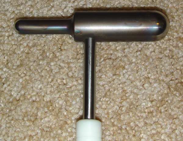
Bumping tool with two polished radiuses. It takes some experience to avoid going too far, so
practice on a scrap before tackling that priceless one of a kind motor.
This actually works best as an intermediate tool between the end bell and a plastic hammer.
Finally, we need to talk about painting. I generally fill little dents and ripples and prime exactly as I would on a car, using body putty and spray cans. However, most of these dynamotors and inverters were painted with black wrinkle paint, which is a real challenge. If you get enough paint film on to wrinkle properly, it drips and sags like a champ on anything vertical! I finally gave up on all the other alternatives and made a Rube Goldberg rotating fixture (below) that spins the dynamotor between five and ten rpm about a horizontal axis. The motor was from a furnace damper control, bought at a hamfest for a dollar. A heat lamp to warm things up and you can get a beautiful wrinkle finish without runs or unwrinkled areas. Some polishing of the nomenclature tag, perhaps some black acrylic paint from an artist/hobby store to repair the background on etched tags (a rubber squeegee can be useful here), and you’re done! If you want perfection, you can get a small package of bright tin self plating solution for three or four bucks and make the numerals really stand out like new.
Closing thoughts...
There is a related subject that probably fits here, and that is the aging and deterioration of WWII avionics equipment. While this factor is not affecting the dynamotors in a big way yet (except occasionally for the small hash filter capacitors that look like micas on each end), the growing age of capacitors and other components is causing a lot of people to look at lowering B+ voltages in an effort to provide at least a palliative measure, for radio receivers if nothing else. It isn't a cure...only replacement with new components can do that...but it provides a "quality of life" approach that extends the usefulness of the sets without more serious surgery. After much testing, it turns out that there is no serious downside to lowering plate voltages in most of these receivers. There is one major reason to keep the B+ near its original design center for a receiver, and that is the audio amplifier stage. Without enough overhead to B+, the audio power available from the set goes down quite rapidly with lower plate voltage. Happily, this loss of power can easily be made up with an outboard amplifier of one form or another. My favorite solution to that is to use one of the interphone amplifiers of the period and wire it in so that the receiver output can be fed into the microphone input.
There are five basic techniques for lowering a dynamotor's output voltage without altering external appearance, none of which could be exactly termed as non-intrusive. Be aware that simply using a 24v dynamotor at 12v isn't a good solution. Reducing the input voltage, while it does reduce the output, generally introduces a significant amount of instability, and the excellent voltage regulation for which dynamotors are well known goes rapidly south at voltages below 75% to 80% of design center.
The four somewhat more traditional alternatives at the moment are outlined below.
1) By the time WWII rolled around, most of the dynamotor manufacturers had settled on some industry standards for frame size, and even went so far as to make some of their components essentially identical. For example, the common frame size for the command set receivers is 310. One thing I have discovered is that later dynamotors with the same frame size had armatures that are sometimes drop-in replacements for the WWII armatures, but have output voltages that range from 120 to 170 volts! I've had particularly good fortune with the postwar AN/AIC-10 interphone amplifier dynamotors, which normally go for very little money, yet their HV output is only 170v, much easier on the receivers. Note that this is luck of the draw between manufacturers, and you can't guarantee it, but tweaks with a lathe will usually make the necessary alterations to get an armature to fit. Issues to be considered include physical size, magnetic gap dimension between armature and stator, and stator field strength, but most of those factors (except physical size) contribute to even lower output voltages than on the original labels. It may be easier to simply swap the whole dynamotor to the old mounting plate, but then you lose the original look of nomenclature plates, etc. You'll have to make an assessment based on your particular case and associated barriers to an armature swap.
2) This second alternative requires the skills of a metalworker. It is also hinges on how the HV winding on the armature is made. The idea is simple, and was introduced by one of the 73 magazine staff back in the late 1960s, but he was focusing on the primary 28v side to allow use with 12v car systems. Basically, you have to rotate one brush around from the 180 degree point to lower the voltage. The catch is the need for the HV winding to be in a particular commutator connection configuration. It requires a new brush holder to be positioned at some angle to the original, the angle a direct relationship to the output voltage desired. There is nothing easy about this alternative, and it requires the "Patience of Job" to get working, but work it does if the winding is connected in such a way that the individual loops are essentially in alternate segment series with each other. Rather than get into the technical aspects to determine the type of winding, it's easier to simply connect a multimeter to one brush and use a probe (preferably with a rounded end) to gently touch the commutator at the 90 degree point while the dynamotor is running. Be careful...this can produce all sorts of negative results if you short the output to ground or electrocute yourself! If you are lucky, you can vary the output voltage by changing the pickoff point with the probe. If it doesn't do that, this method won't work and you will have saved yourself a lot of work.
3) The cleanest alternative, but by far the most time consuming and difficult, is to rewind the HV side of the armature to have a smaller number of turns. Note this requires a high degree of interest in experimentation, and/or the friendship of a shop that rewinds larger motors. Most of them aren't interested in working on such small motors, and will simply price any work out of reach just to get rid of you. It is possible to do it yourself, but requires enormous patience and organization (each of the multiple windings needs to be carefully tracked and labeled for it to work properly) and for most folks this may be a bridge too far. For the persistent (dare I say stubborn?) it can provide a number of hours of intense satisfaction for those so inclined. One beginning step is probably to go to a motor rewind shop with the dynamotor and tell them what you want to do. They may allow you to at least watch the process on one of their larger motor jobs. If not, a good text on the subject is essential in any case. I would only do this if I wanted to keep the receiver entirely original, and given the amount of work involved I would recommend it be preceded by measuring distortion, large signal handling capability, and overall gain (less the PA section) at a number of B+ settings to determine how far you could lower the plate voltage without significant impact. As a data point, following Dave's (AB5S) initial suggestion, my RAT sets work reasonably well with 28 volts on the plates, but then I've long since established realistic expectations for their performance. For them, I simply jumpered the input to the output under the base and unhooked the B+ from the dyno. The virtual armature mentioned below should rein in some of the drawbacks of going with a lower B+.
4) There is a fourth alternative that I have used for the command receiver dynamotors that gets the voltage down to 170 volts DC, and that has been to transplant an armature from a 1950's interphone amplifier supply for the AN/AIC-10, called the DY-77/AIC-10. You'll have to check the dimensions, because some drop right into a WWII command receiver dyno, and some won't. Generally if they are the same manufacturer, they will, and sometimes even if they aren't. You'll just have to try yours and see.
I've done some work with series regulators, but there is no miracle here - Ohm's law requires the dissipation of some 5 watts or more of power, not to mention the problem of finding a device that will drop 100-150 volts, will fit into the dynamotor base, and use the baseplate as a heat sink. The baseplate gets pretty warm with 5 watts pumping into it, and it in turn heats the entire dynamotor to uncomfortable levels when you add it to the normal operating temperature of the running dynamotor in the test rig I put together. One approach would be a switching regulator, but I haven't had enough time to delve into that approach. A preliminary sizing suggests it won't fit into the narrow base of the dynamotor, but if I can find the right devices, it may be possible. It is certainly possible to do the job with an outboard regulator, but the only thing that buys you over a complete outboard power supply is the privilege of hearing the dynamotor whine, and hiding such a construct isn't easy.
Another option that holds more promise is using DC to DC converters. There are now several available in the range of $10-$15 that have output voltages up over 200vdc with 14/28vdc input, but you do lose the lovely whine of a real motor. I bought a couple of latest generation modules recently for evaluation as a drop-in replacement for a command receiver dynamotor armature. They offer DC output voltages from 70 to 220 volts DC from 14 and 28 volts DC at 20 watt output levels, and I've managed to squeeze them onto an armature shaped Delrin mount fabricated for this purpose. An unfinished peek at progress is located here.
End