The prototype tunable VHF ARC-5 system shown on the flight deck (see VHF Prototype) was designed to use a single antenna for both receivers and transmitters. Chasing every db of loss was important in those days, as well as making the system easy to service. Obviously with the SO-239s on all the equipment, ARC could have used the stiff RG-8/U coax, but that wouldn't have been up to their usual elegantly engineered standards, so they designed delicate little hardline jumpers to connect sets that were mounted in the same ARC-5 rack. Two different sizes were required, one for a pair of receivers and a longer length for a pair of transmitters.
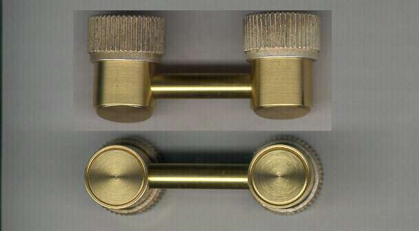
Making these turned out to be a little easier than it first appeared, helped by the discovery of some right angle coax fittings at a hamfest that had perfectly matched knurled thumbscrews. A little 'surgery' with the milling machine freed them from their former captivity, as well as the center pins and insulator. From there on, it was a simple matter to turn new bodies to size from brass stock and install the connector tube, made from brass rod. The rod was bored to the same size as RG-59 inner insulation, and teflon insulated bare copper wire slid into the bore. The reason for the teflon is that all the soldering must be accomplished after the wire is installed, and teflon is one of the few dielectrics that will accommodate the heat without damage.
Assembly was a matter of soldering the inner conductor to the back ends of the pins, then soldering the connector tube to body interfaces. When those tasks had been completed, a hipot test showed everything was hunky dory, so the rear caps were then soldered on. Silver plating completes the job. One cosmetic finishing touch in the planning stages are stamps to match the original ARC logo and part number stamped on the end plates.