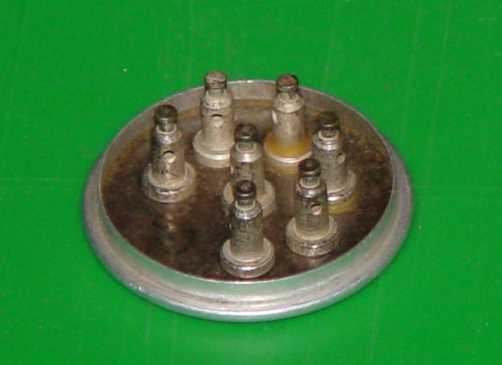
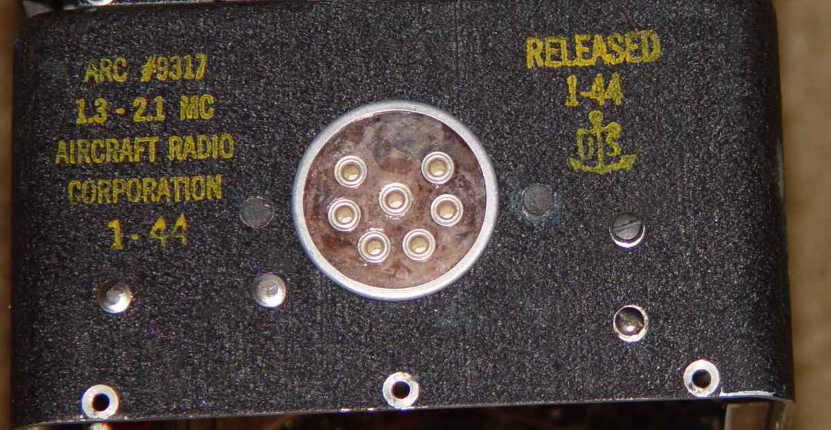
NOS T-17/ARC-5 rear connector
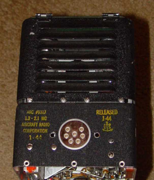
This transmitter is typical of several "hammed" MF ARC-5 transmitters (T-15, T-16, and T-17) that I have seen over the past twenty years. Modifications on this one included replacement of the rear connector with an octal socket, removal of both internal relays, removal of the R-71 filament paralleling resistor and its mounting clip for the 1629 eye tube, and removal of any wiring not required for a bare bones transmitter. Of all the mods, the ones on the rear are the most formidible to restore to halfway original appearance, so that's where this page is focused. The rest of the mods are simple to fix and involve reinstalling missing parts and wiring.
Luckily the person who modified the transmitter used an octal socket that fit into the original connector hole without removing any metal (except for the necessity of drilling two 3/16" mounting holes), so the new connector above was simply installed like a large rivet and the exposed aluminum ring curled over with a die.
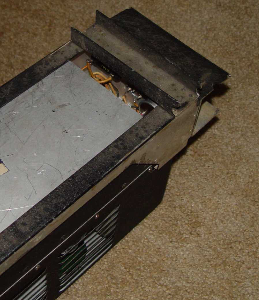
Getting the connector oriented so that the female pins will properly align with the male pins in a rack required a bit of fiddling and the use of a hacked up transmitter rack that I sometimes use for test purposes. After applying a small amount of high strength epoxy* to the periphery of the connector, it was pre-inserted into the male plug in the rack and the transmitter then slid onto the rack. A modified bottom plate provided visual access to the interior so that the connector could be centered on the hole as the transmitter was slid on. The plate also stabilizes the transmitter at the proper orientation. Doing this without a bottom plate in place produced a slight "rocking" that could affect alignment on down the road.
*This needs to be a high quality product that is not out of date, not dime store instant glue. Prep involves removing any oxidation from both the connector and inside of the connector hole. You don't want the bond to fail in the subsequent riveting operation, which uses a special die on the inside of the transmitter and a "bucking foot" on the outside to squeeze the "rivet" using a C-clamp. Keeping a steady pressure on the bucking foot during the procedure reduces the chance for bond breakage.
Once the epoxy was cured for a couple of days, the transmitter was carefully pried from the rack to avoid breaking the epoxy bond, and a special die made on the lathe was used to set the thin aluminum "rivet" rim that stood .060" proud above the inside surface of the chassis.
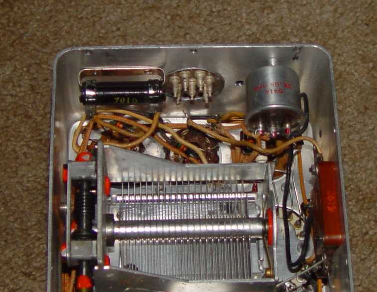
Next step is installing a couple of small aluminum "top hat" plugs in the screw holes drilled for the octal socket, using epoxy. The depth of the plug is designed to match the existing bare panel thickness...not the panel thickness of the panel plus the paint film. That insures that after adding the paint, the surface will end up at the same level as the original paint. The heads of the plugs have been coated with an aluminum blacking compound similar to gun bluing to prevent oxidation prior to painting.
Next step is painting the resistor mount rivet heads satin black. Some black paint stippling work and it will look much better.