I suppose everyone who does this sort of thing has a preferred way of refilling or restuffing the command set "can" capacitors.
This just happens to be mine. One thing to keep in mind is that ARC used two different materials for the cans over the years that they made them - aluminum
and cadmium plated brass. That won't affect the simple removal of the tops, but will affect the stuffing mentioned further down below
in terms of connecting the new capacitor to ground. Some flare tube cutters have a wide enough recess in the backing rollers to allow moving the cutting
disk up to just under the lip of the capacitor. If the recess is at least .090" wide by .090" deep, you should be fine.
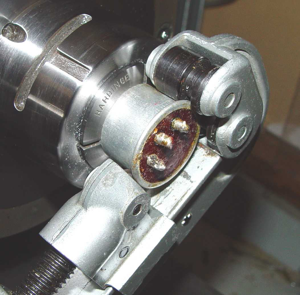
Unless you have a collet similar to that shown, you still need something in a soft plastic to grip the capacitor while
you turn the cutter, because you will inevitably get slight movement of the capacitor and some scuffing in the process.
If the plastic "collet" extends almost to the lip, you can protect the capacitor from the rollers as well, though a bit
of tape will probably protect that in a pinch. This example is a soft aluminum drawing (a worst case compared with the
harder brass shells in many of the sets,) and shows the edge of the rollers imprinted on the capacitor
housing that can result from too many "rings around the rosie" without such protection.
I like AB5S' approach of using a heat gun to melt the wax visible in the above photo. The innards can then be easily removed with a dental pick. The deformation at the parting line can then be removed with a burnishing tool - basically a polished cylinder held against the inside of the wrinkled edge. On the other hand, I prefer a bit of indentation to provide an increased depth of an annular ring of epoxy after the rebuild. After the epoxy cures, a bit of sanding and a finish coat of chrome bumper spray paint to restore the look of the cadmium plated original, and you're through!
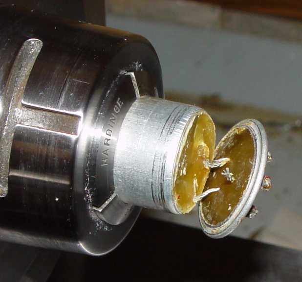
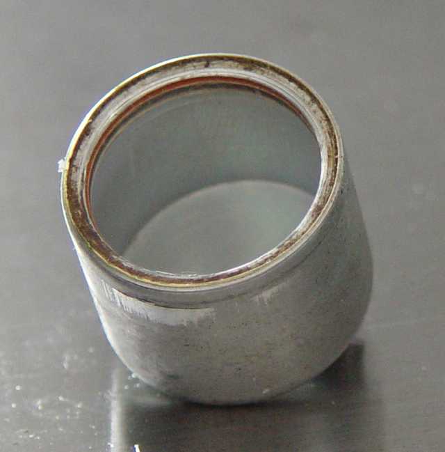
The electrolytic capacitors in the command receivers use a different approach to construction and require a bit more effort to take apart.
After removing the top using the flare tube cutting tool, you are faced with the picture above. The reddish disk with the eyelet connection on top is actually made from red pigmented rubber - basically a red rubber washer 1/8" thick, intended to slow the evaporation of the electrolyte. The next layer underneath that is a similar thickness disk of phenolic. This is where the delightful smell comes from - anyone who has drilled or machined phenolic is familiar with that lovely aroma. It's also where the yellow "corn meal" swarf comes from as you drill down through it. It's relatively harmless as long as you don't try to eat it in large quantities. Beneath that is a paper insulated rolled capacitor.
Henney's Radio Engineering Handbook of the period advises that this design is the latest in technology for electrolytics (1941), and is composed of tightly controlled thickness aluminum foil that has been etched to increase the surface area, and the electrolytic portion of the paper dielectric is reportedly just dilute boric acid! Shades of "Twenty Mule Team Borax" house cleaning products...
Placing a drop of the fluid in the can on a freshly sanded steel surface overnight produced fairly quick rusting, so it is indeed water based rather than oil based. Though not relevant here, Henney also advises that normal oil filled paper capacitors (this would apply to the rest of the can capacitors in the command receivers) use either castor oil, cottonseed oil, or "transformer oil" (whatever that was in 1941) as the additive to the paper dielectric,
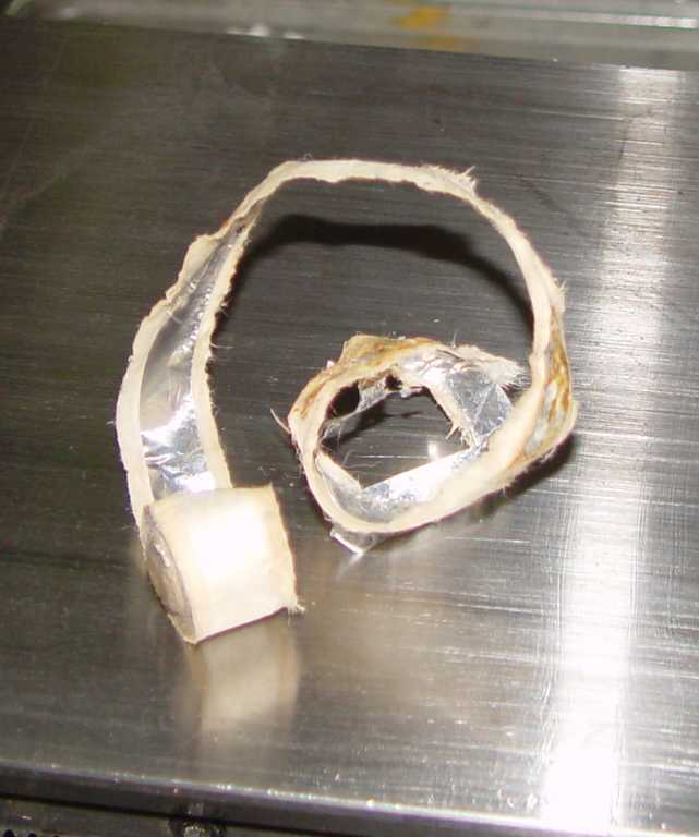
Drilling down the center is actually the fastest way to remove the insides. Use a decent workholding device (a collet is best to prevent deformation of the thin can). Then use a 1/2" drill bit in a drill press and slow speed to drill down .750" from the top surface. If it stops moving downward with moderate pressure, clear the tip of the drill of the wadded up aluminum foil and paper. Not exceeding that depth will keep the drill tip just above the bottom of the aluminum cup, which will then be revealed by careful use of a dental tool with a hook on the end. Try to resist the temptation to use the sides of the cup as a prybar point - it is very soft and will deform in a flash. If the top rubber and phenolic disk resist your removal efforts, try cutting one side with a Dremel and an abrasive disk to relieve the pressure, or run a 7/8" hole saw down the center for the top quarter inch or so. With a lathe it is dirt simple - just use a boring tool and bore out the top two disks almost to the metal edge. The capacitor itself should then lift right out with little effort.
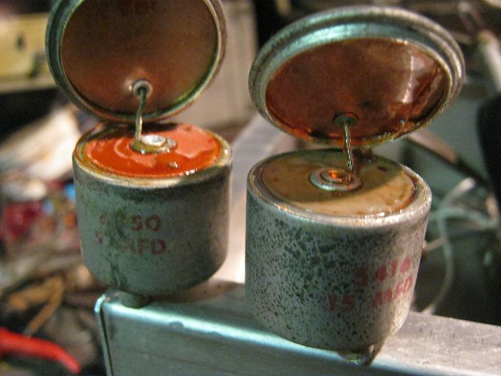
At the bottom of the capacitor can is a slim (.030" thick) disk of phenolic to insulate the bottom side of the rolled capacitor from the bottom of the can. The aluminum container for this concoction, including the top rubber plug, is pressed into the brass shell of the capacitor. The connection of the outer foil to the aluminum cup is apparently just direct contact with the can for 360 degrees. That is likely the problem with loss of capacitance. The foil usually shows signs of oxidation, this long after manufacture. The inner foil connection is made through the eyelet on top.
I did not remove the pressed-in aluminum cup from either capacitor since everything inside came out so cleanly, but there is no other apparent ground connection - which begs the question of why there is a ground solder blob between the two screw posts on the bottom of the capacitor. I hated to destroy one of these two examples to find out, since they are prime material for restuffing. Thanks to a note from K1LKY, it wasn't necessary. Solder sucking the blob off the bottom revealed a hole with no wire lead protruding from it. The capacitor case was simply sealed with the solder. That makes the way clear to drill a hole through that brass outer can sealing hole and through the bottom of the aluminum can for the ground lead of the restuffed capacitor, then resoldering the ground lead as in the non-electrolytic capacitors.