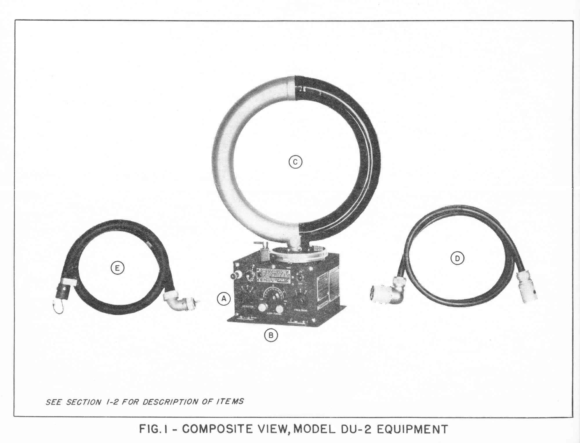
Original Coupling Cable between loop and receiver (Item E on left)
Almost every time I have walked by the DU-2 and RU receiver in the "flight deck", I briefly fret about the jury-rigged coupling cable between them. In thirty years of looking, I have never seen an original one in the flesh, except in the Kingfisher float plane now suspended above the Enola Gay B-29 at the NASM Udvar-Hazy museum outside of Washington DC. I finally decided to bite the bullet and attempt to recreate something that would pass the "looks like it" test. In the process I made some modifications to make fabrication easier, hopefully without disturbing either performance or external appearance. There is nothing magical about these simplifications, and others may see alternative ways of accomplishing the work even more quickly. They are described simply to provide some ideas for your own implemntation efforts.
It was not at all clear why an entire unique cable assembly was designed for this set, other than it may have been carried over from what was the original Navy Model RDF-1, designed and patent submitted by Charles W. Hicks on July 12th, 1935. Creation of a custom built coaxial cable for the set may have grown out of a desire to lower line losses between the loop and receiver up to the RDF-1 limit of 8.0 MHz. The most significant clues appear in these two snips from an analysis of the RDF-1 in a Naval Research Laboratory training manual dated 1936:
[snip] "One Direction Finder - receiver coupling cable, 24" long, 3/8" diameter, weight, 0.32 lbs."
and"The direction finder - receiver coupling cable is a low loss shielded transmission line provided for connecting the direction finder output to the antenna terminal of the radio receiver. The 24" coupling cables supplied with Type RDF-1A direction finder equipments are designed for general installations in various types of airplanes where the Type Ll130-B direction finder can be mounted in close proximity to the radio receiver. Special coupling cables, of various lengths are supplied with this equipment allowing it to be used in the various types aircraft. Since these special cables have an outside diameter of 5/8" they are supplied with an auxiliary fitting which adapts them to the output bushings on the direction finders. Due to their larger diameter, the capacity of these special cables is of the same order as that of the standard 24" cables, but their weight is increased to 0.66 lbs."
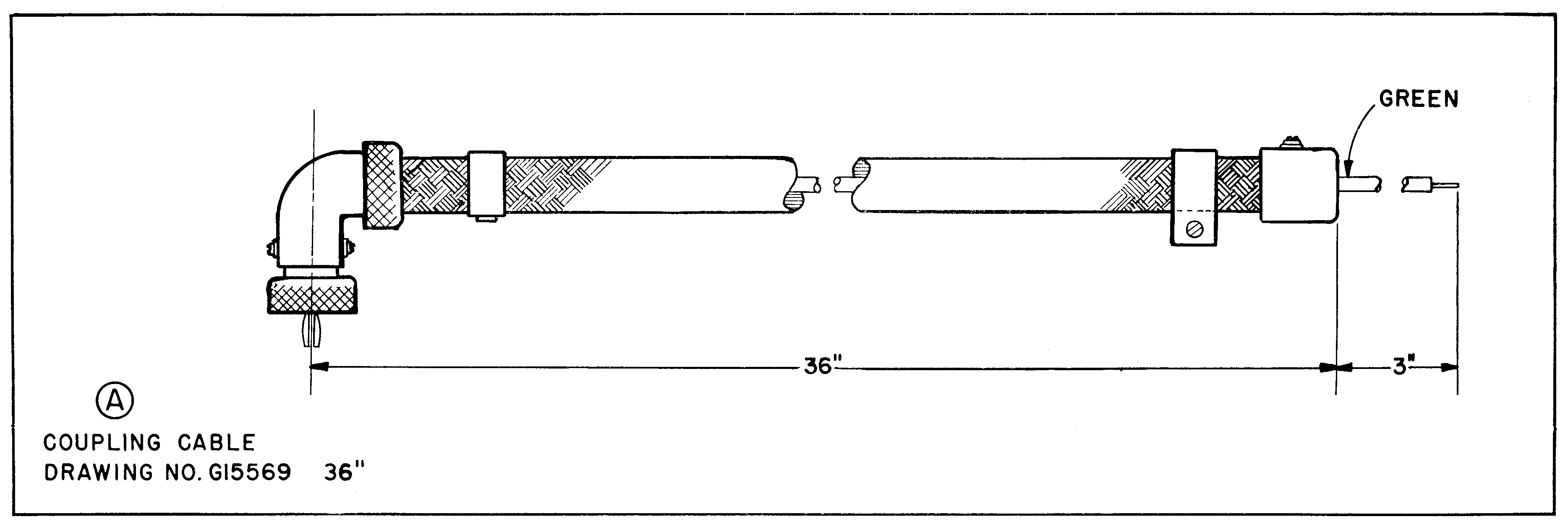
The excerpt above vaguely describes the need for an "auxiliary fitting" in the knurled connector interfacing the loop output, due to two different OD sizes of cable mentioned above. This may or may not explain the otherwise inexplicable double threaded knurled thumb screw construction of the cable used with the later DU, DU-1, and DU-2 contracts that ended as late as 1942. See drawing below.
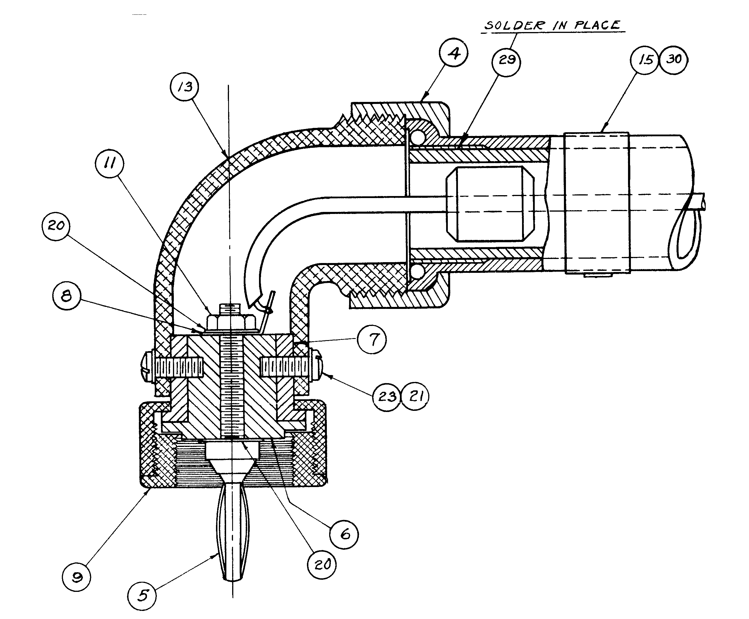
The flexible cable for the later loops is nominally trade size 1/2", with an outer diameter of approximately .680", close enough to .625" to call it good. It does not appear unreasonable for Bendix to have simplified the parts count by settling on the same cable design as the longer RDF-1 cables to serve both the 36" and 84" DU variants offered in WWII.
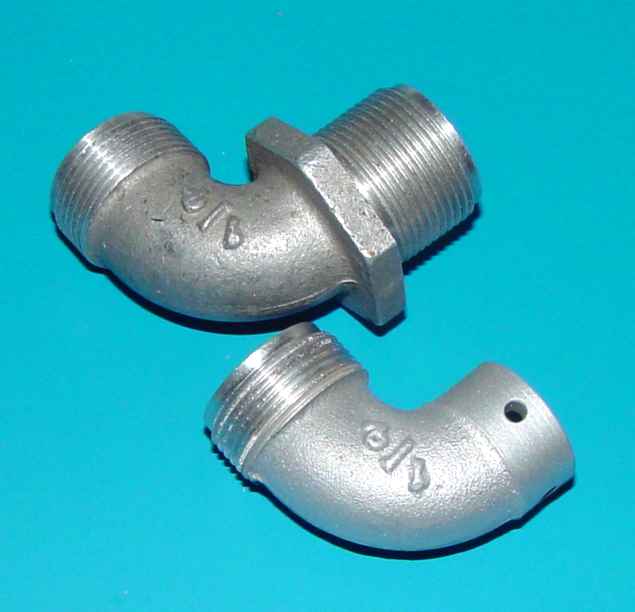
The need for a low loss cable has no elaboration, nor what the specific capacitance should have been. More detailed cautions for meeting specific targets are reflected in the later AN/ARN-6 and AN/ARN-7 manuals because of phase shift concerns, but apparently not in the documentation back in the mid-1930s. The construction of the cable is curious - the use of a few little beads inside the braid covered flexible conduit seems suspect in terms of providing a consistent transmission line profile demanded of later coaxial line. Perhaps the discreet insulators (quantity of nine over the length of the shorter 36" coupling cable), fastened securely(?) to the inner conductor with something called Superla wax (which appeares to have lost a -tive suffix to some marketing sleight of hand), somehow leveled the response. Perhaps good commercial coaxial cable was simply unavailable in 1934 when the RDF-1 development was mostly accomplished. The manuals allege that R-108 provides the fundamental impedance of the plate load at 1,000 ohms, which driving a 3 foot cable seems low enough to avoid any impedance problems up to the DU limit of 1,600 kHz. Regrdless of the technical puzzlements, it is not the first time that an inordinately complex conglomeration was carried through for years due to engineering inertia...witness 1936 Ford ash trays being used for the first Boeing YB-17 prototype and continuing as a "requirement" in Boeing military aircraft well into the 1950s.In an attempt to assess the feasibility of replicating the connector at the loop antenna end, I was somewhat discouraged with what to do about the cast aluminum elbow that forms an essential part of the assembly. A bit of research suggested that it may have been a special casting that was adapted from the famous "Breeze" series of lightweight electrical conduit fittings introduced for aircraft in the early 1930s. Those fittings eventually morphed into a recognized Army/Navy standard, the AN 3062-* elbow. Below is the generic AN 3062 Size 8 fitting that I decided to use to begin fabricating a replica. The size scaled almost exactly to the Bendix drawing in the back of the DU-1 manual (the drawing was deleted in the later DU-2 manual.)
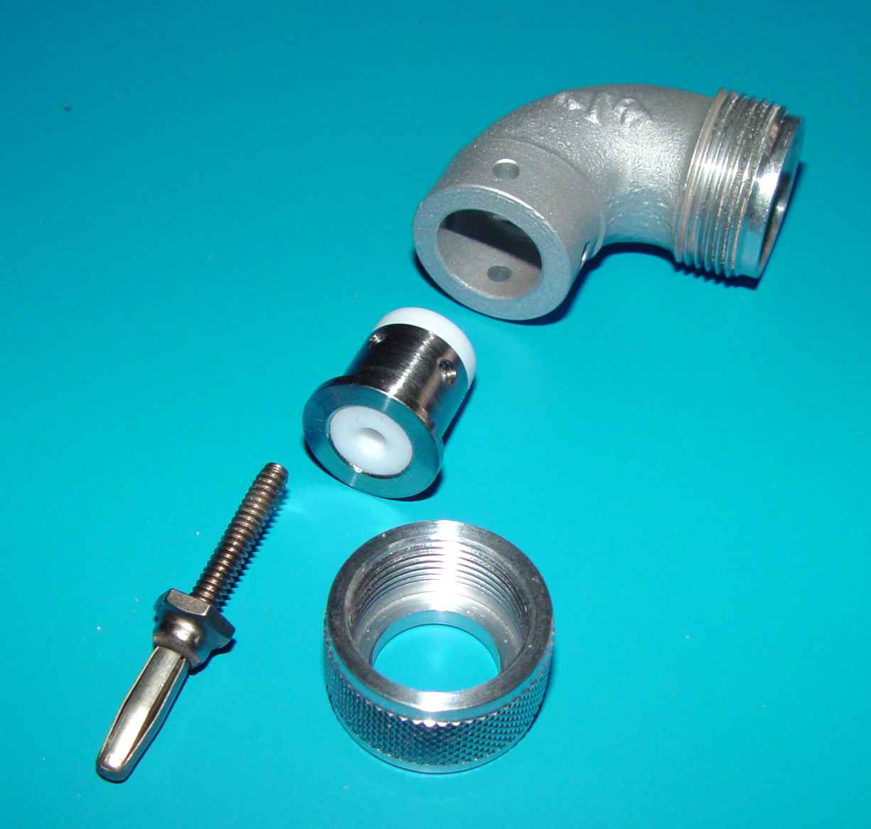
Shaping one end of this elbow to resemble the original Bendix casting turns out to be a bit more complicated than it first appeared. The primary difficulty is in doing something with the 10° internal taper in the end that needs to bored into a cylindrical shape. There is more than enough material in the end to match the original DU drawing, but much of it must be machined off, while maintaining the external profile back to the right angle curve in the elbow. I'll be happy to share the gory details of the way I approached it by email, but suffice it to say, the final product ends up like the picture below. Also shown is the insulated insert that provides a foundation for the banana plug. The dimensions of all of these parts are in a link at the end of this article. I expect cobwebs to grow on that link, but it's there for someone a hundred years from now who might attempt to replicate the cable.
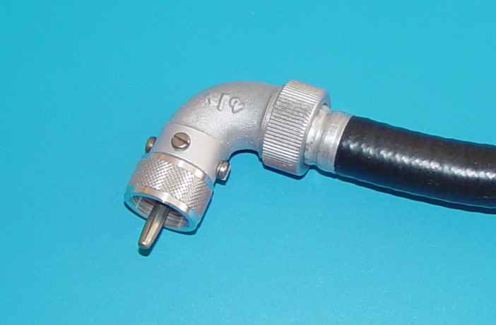
The completed assembly is shown below.
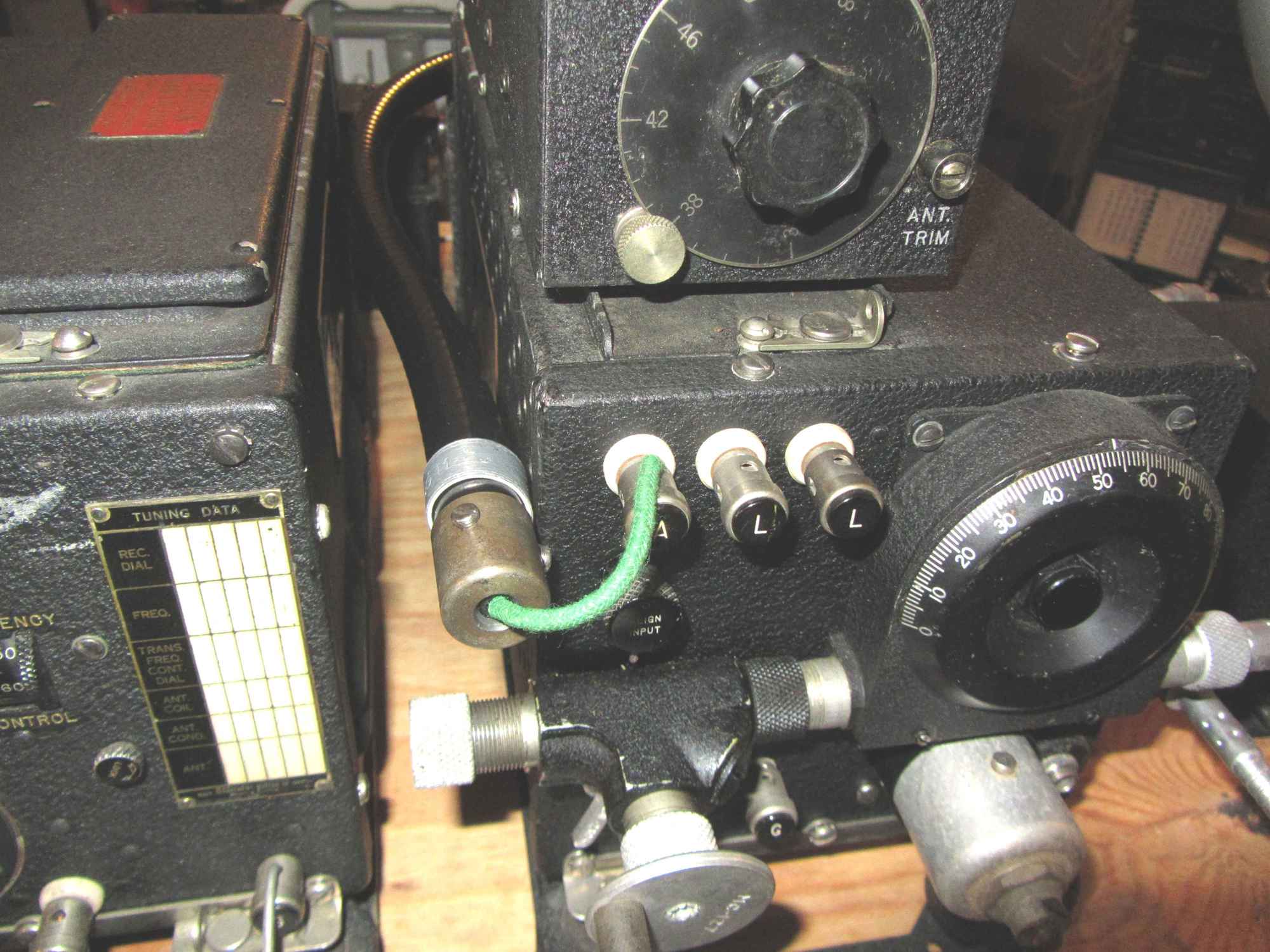
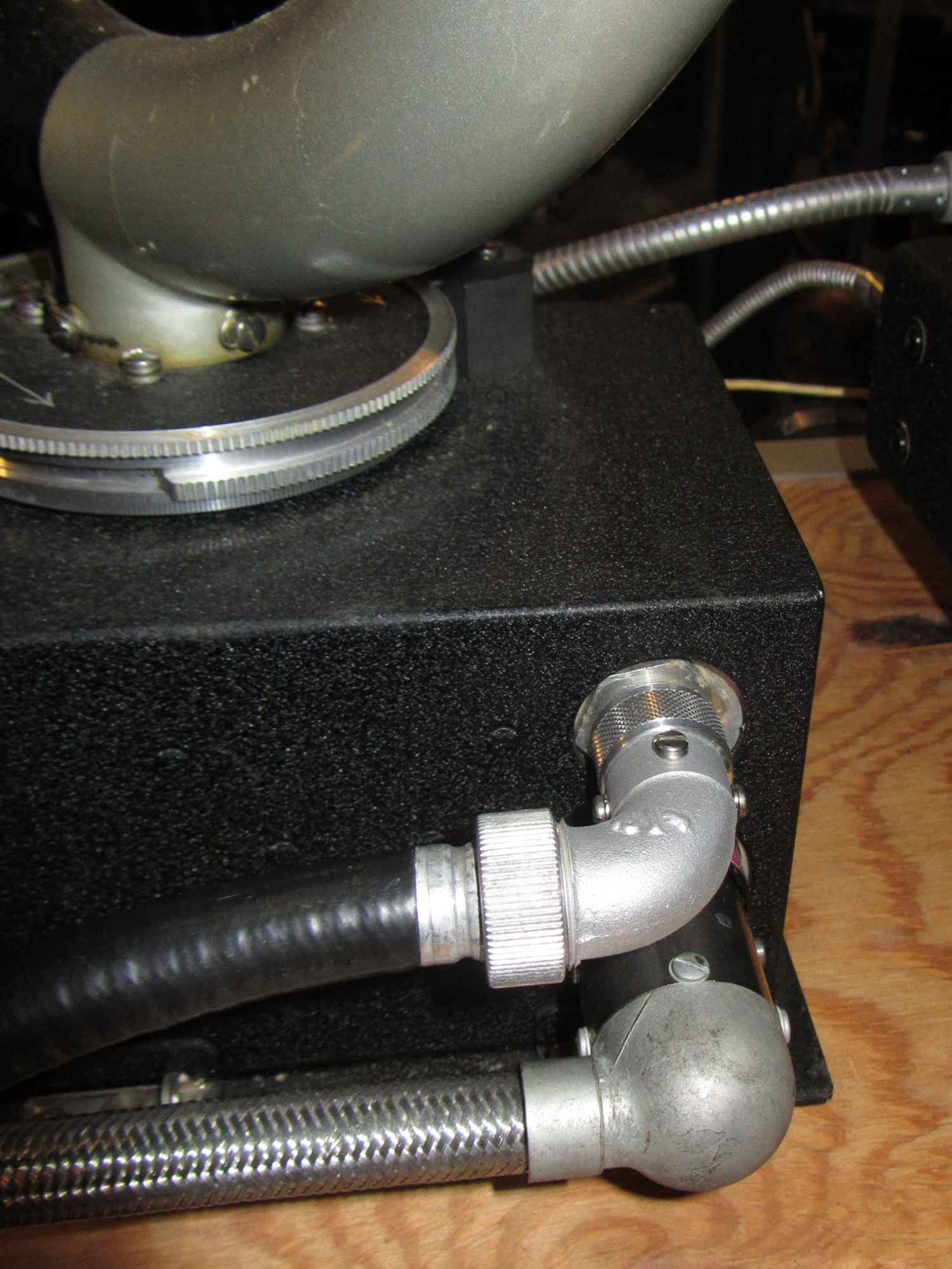
The other end of the cable reflects the same complexity that marks the loop end, largely driven by the configuration of the shop-made "coaxial cable" coming into it, and the transition at the very end to a single 3" open wire to feed the RU receiver antenna push post. Interestingly enough, no attempt appears to have been made to connect the braided shield of the cable to the ground of the receiver. The coaxial outer braid/inner flex armor is essentially an open-ended Faraday shield that floats at the receiver end. The clamp to attach the cable to the left side of the receiver clamps around the vinyl covered flex cable, so no bonding occurs at that point.
Like the loop antenna end, I made some internal changes to make it simpler to assemble the cap, while retaining the original external appearance. I did that by extending the stripped and tinned part of the "green" open wire through a thin brass tube in the center of the Teflon insulator. The color green is mentioned in an overall drawing of the cable shown near the top of this page. I have no clue why it was specifically called out as that color. At the end of the brass tube is a mushroomed head to resist pull-out force on the wire. A dab of solder on that end bonds the wire to the brass. Once the wire dives out into the flex tubing, I attached it to the RG-213/U cable inner conductor with a compression splice. That eliminates the original transition using an air space and solder lug under the cap at the end. It seems to work fine. At the loop end, both the RG-213/U braided shield and the spiral zinc plated flex core are mechanically connected to the elbow body to provide the Faraday shield to the receiver.
The finish on this end cap is specified on the original drawing as N.P., shorthand for nickel plated. The photos in the manuals clearly show that the color is dark compared with the elbow on the other end, presumably to eliminate shiny diversions for the operator, so apparently the original finish was black nickel plate. I'm not sure what the original material was, but it was most likely brass. I decided to make mine from stainless steel and use a cold stainless blackener from Caswell. It's less expensive than plating and you can adjust the color with the immersion time.
This is probably a good point to introduce the problem of finding flexible conduit that is "close enough" to WWII versions used in aircraft and shipboard applications. Every so often I have made a limited attempt at going through a bunch of the commercial flex conduit offerings to see if I could find something reasonably close, but it has only been recently that I located products that gets close enough to meet the need. The one I settled on (6100 series from Kaf-Tech, a part of Atkore International) is not a precise match - it has the usual light gray color, the OD is a few thousandths larger (at .700" +/- .010") than the original .690"(ish), and there is no woven braid covering the zinc galvanized core. On the other hand, the core spiral pitch is pretty close and with a coat of gloss black vinyl dye, it's hard to see a difference side by side with an original cable. It's made in several locations in the USA - the 25 foot length I bought to assess was manufactured in Florida. Through the magic of weird standards, the "trade" size is marked as 3/8", but its ID is actually .494" +/- .010". Go figure... The light gray color is easily remedied by a spray can of gloss black vinyl dye (I used VHT, but there are several competitors). Where it gets complicated is replicating the function of a well designed transmission line. The original had several cross-sectional discontinuities that augur against any significant claim to broadband response, so it seems to me that the primary driver was probably simply to reduce noise and/or feedback around the loop amplifier and from there forward to the receiver. In that function it seems reasonably successful, even with my "unauthorized" modifications.
Mounting the receiver end is generally optional to the installer, but the manuals include an option for keeping the coaxial cable above and parallel to the front panel running from the right to left. The logic is not explained, and works reasonably well if the loop is mounted above the receiver, where there is room to corkscrew the cable around so that it comes from the right side of the receiver. Locating the loop to the left of the receiver also works well with that approach. Since mine did not match that configuration, I mounted it on the left side of the receiver, with the coax parallel with the side of the receiver. I don't think it makes any difference performance-wise.