RU/GF Junction Boxes with Connector Numbers
One of the frustrating tasks associated with putting together an RU or RU/GF set is the bewildering numbering system on the connectors.
There doesn't appear to be standard Navy five digit numbers mapped to the two and three digit numbers engraved on the connector backshells.
This seems to have derived from the original GF and RU set architecture back in 1932, where the connectors were given the number of the entire cable.
Thus Cable 37, for example, would have "37" engraved on each of the connector ends, presumably to facilitate final connection.
In an attempt to help sort out these numbers, it occurred to me that an easy method might be to simply have a series of photos,
one of each of the junction boxes associated with a given set - since most, if not all, cables pass through the junction box. These
junction boxes have had different five digit numbers over the course of time - the earliest I have a record of is CBY-23011 for the GF/RU-2, and CW-62017
for the last RU, RU-19. If you own or have access to one of these junction boxes that is not pictured below (or have a clearer photo than the ones here)
please e-mail the photo to

along with your
preference for attribution if so desired. I'll add them to the list below as they come in.
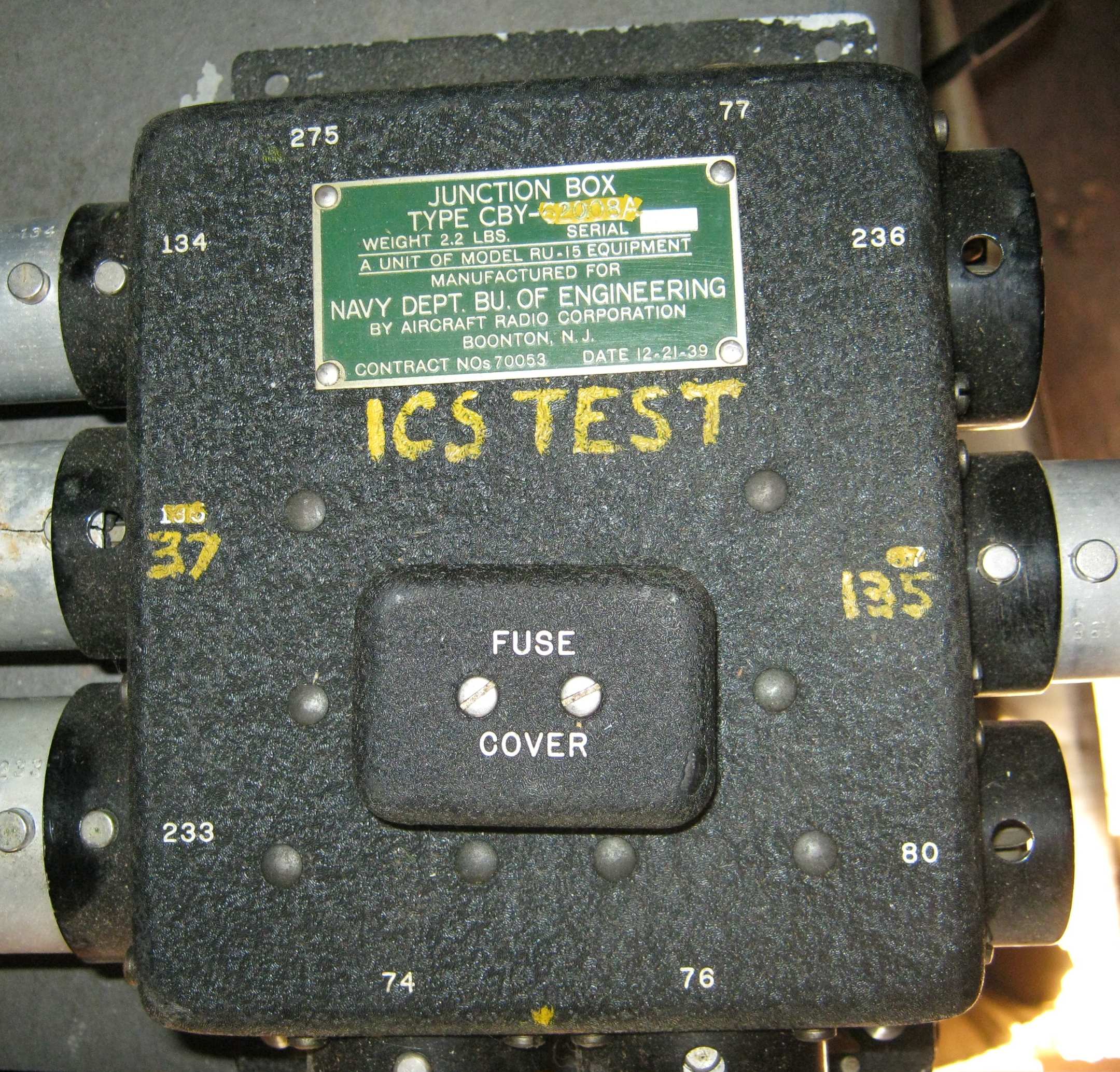
RU-15 Junction Box, courtesy AB5S
| Connector Number |
Purpose |
Number of pins |
| 1215 |
14/28v Primary Power |
2 |
| 37 |
Transmitter Control Box |
8 |
| 741 |
Aux Power (LM-*, DU-*, ZB-*, etc.) |
5 + guide |
| 761 |
Aux Power (LM-*, DU-*, ZB-*, etc.) |
5 + guide |
| 774 |
Antenna Relay |
2 |
| 802 |
Extension Control Box |
7 |
| 1345 |
Dynamotor |
6 |
| 135 |
Receiver Control Box |
7 |
| 233 |
Receiver |
11 |
| 2364 |
Transmitter |
9 |
| 275 |
Remote Antenna Control, or Throttle Switch |
phone jack |
| Notes for both RU-14 (14v) and RU-15 (28v) installations |
| 1Both 74 and 76 provide ground, B+ and filament. 76 also provides negative bias and an extra B+ pin. |
| 2If extension control box not used, then subsititute plug 3292 must be used. |
| 3If RU receiver to be used without a GF transmitter, then substitute plug 3290 must be used. |
| 4Navy type plug 77 is used for the junction box to antenna relay cable. In the SCR-183, |
| the junction box to antenna relay uses an Army Type PL-77. These are not the same plug, though they are similar. |
| 5Not shown on junction box is Plug Number 121, which is primary power directly to the dynamotor. |
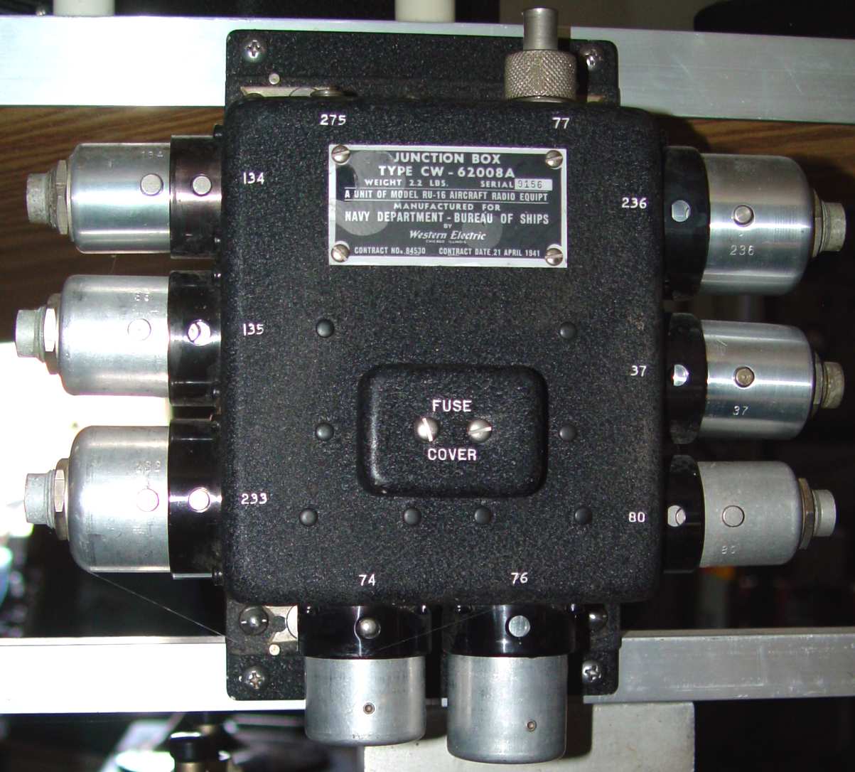
RU-16 Junction Box
| Connector Number |
Purpose |
Number of pins |
| 1215 |
14/28v Primary Power |
2 |
| 37 |
Transmitter Control Box |
8 |
| 741 |
Aux Power (LM-*, DU-*, ZB-*, etc.) |
5 + guide |
| 761 |
Aux Power (LM-*, DU-*, ZB-*, etc.) |
5 + guide |
| 774 |
Antenna Relay |
2 |
| 802 |
Extension Control Box |
7 |
| 1345 |
Dynamotor |
6 |
| 135 |
Receiver Control Box |
7 |
| 233 |
Receiver |
11 |
| 2364 |
Transmitter |
9 |
| 275 |
Remote Antenna Control, or Throttle Switch |
phone jack |
| Notes for both RU-16 (14v) and RU-17 (28v) installations |
| 1Both 74 and 76 provide ground, B+ and filament. 76 also provides negative bias and an extra B+ pin. |
| 2If extension control box not used, then subsititute plug 3292 must be used. |
| 3If RU receiver to be used without a GF transmitter, then substitute plug 3290 must be used. |
| 4Navy type plug 77 is used for the junction box to antenna relay cable. In the SCR-183, |
| the junction box to antenna relay uses an Army Type PL-77. These are not the same plug, though they are similar. |
| 5Not shown on junction box is Plug Number 121, which is primary power directly to the dynamotor. |
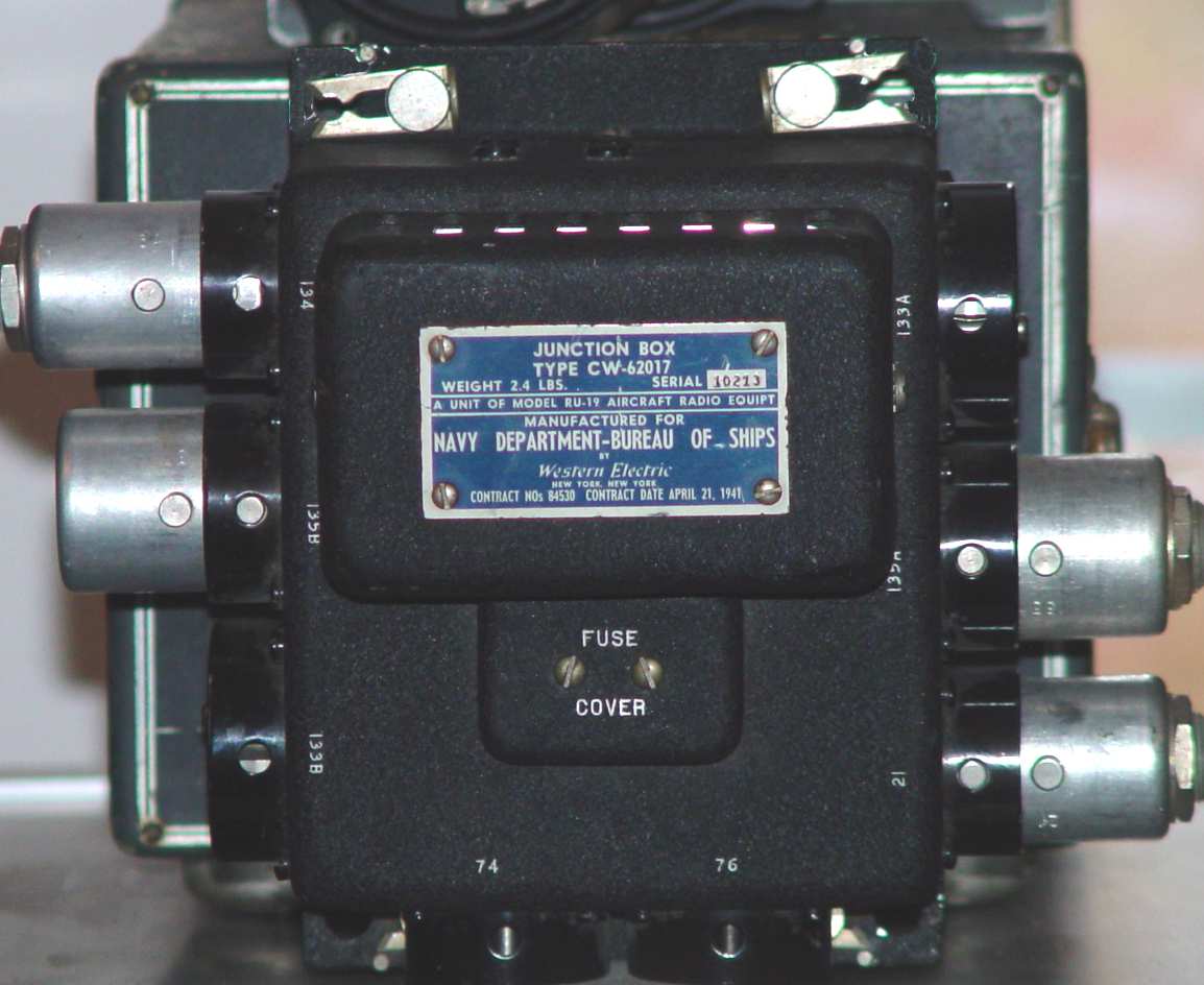
RU-18/19 Junction Box
| Connector Number |
Purpose |
Number of pins |
| 211 |
14/28v Primary Power |
2 + guide |
| 742 |
Aux Power (LM-*, DU-*, ZB-*, etc.) |
5 + guide |
| 762 |
Aux Power (LM-*, DU-*, ZB-*, etc.) |
5 + guide |
| 133A3 |
Receiver A |
10 + guide |
| 133B3 |
Receiver B |
10 + guide |
| 134 |
Dynamotor |
6 |
| 135A3 |
Receiver A Control Box |
7 |
| 135B3 |
Receiver B Control Box |
7 |
| Notes for both RU-18 (14v) and RU-19 (28v) installations |
| 1Used on the original GF/RU-2 in 1932! |
| 2Unlike the RU-16/17, both 74 and 76 are wired the same, and both provide the bias and extra B+ pin. |
| 3The A and B refer to the connections for two receivers. For example, 133A is the same type of connector as 133B. Ditto for the 135A & B. |
Return to AAFRadio Documents