Web Page Under Construction!
AN/APA-6 Pulse Analyzer
©2019
This is the earliest of the dedicated radar pulse analyzers that began development in the U.S. at the beginning of WWII. It replaced an airborne "laboratory
setup" that included an H-P audio oscillator and a Dumont oscilloscope, used to produce Lissajous figures to establish the enemy radar pulse rate. Different
enemy radars, even of the same type, used slightly different pulse rates, and could be identified with fair accuracy by being able to examine the pulse characteristics.
It consisted of two units (plus an internal power supply), shown below:
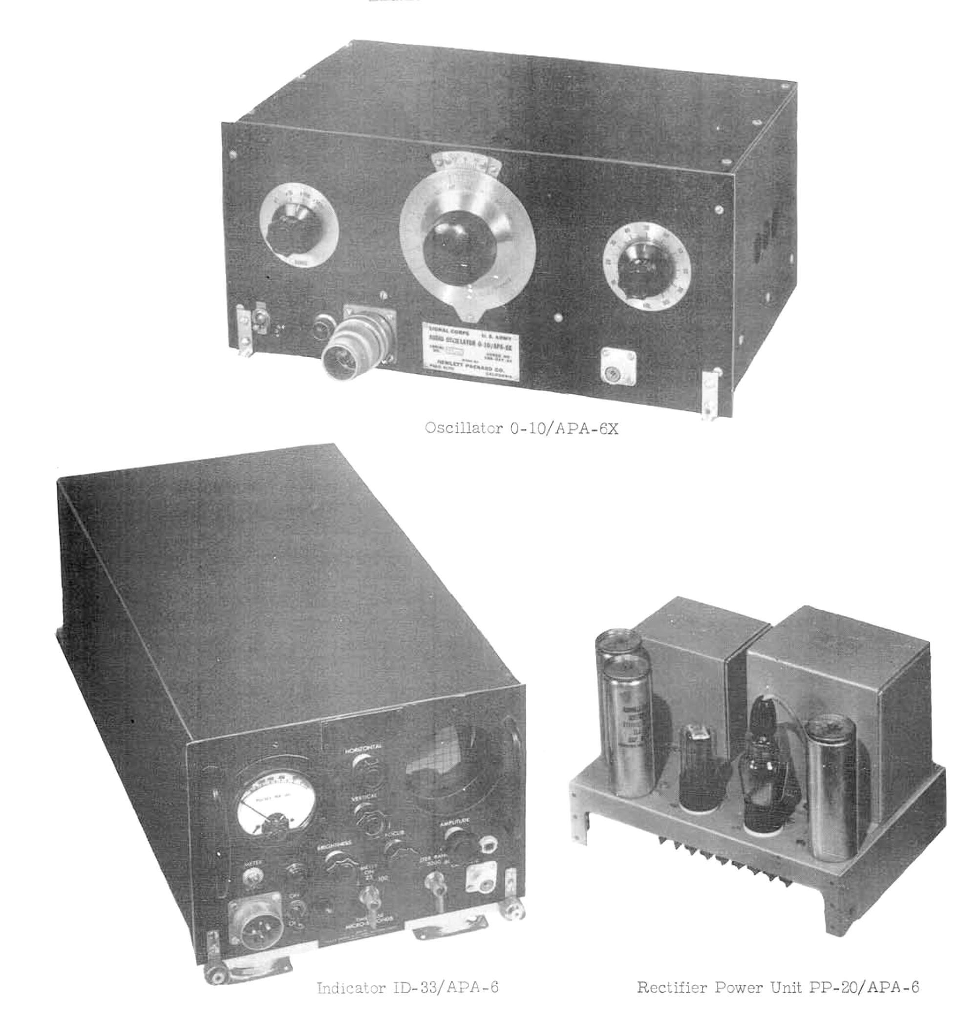
Complete pulse analyzer system as of 1 December 1944. Note that this shows the ID-33/APA-6, not the APA-6A. The differences between
the two airborne units seem minor except for the replacement of the 400Hz power supply with a heavier one that accepted
60-400Hz power, a shock mount change to accommodate the heavier shipboard AN/SPA-1, and a scope graticule revision.
The appearance of the O-10/APX-6X in the directory photo above is a curious thing, as it is not shown in later directory descriptions of the AN/APA-6A.
The "X" suffix denotes an experimental or developmental model that may or may not become permanent. It does not appear in the preliminary manual
for the AN/APA-6A and AN/SPA-1 (Navy equivalent) equipment that is undated (A single page Revision 1 in the back is dated 21 May 1944). The manual does
mention the option of using an audio signal generator for more accurate pulse frequency measurement, but doesn't list any details of its nomenclature.
That complete manual is located here.
Apparently the O-10 oscillator was abandoned in the move to the "A" version of the analyzer. The only conclusion that I have reached is that the
precision of the oscillator frequency compared with the meter roughly reflecting pulses per second turned out not to be useful for the majority of ferret work.
The replacement for the ID-33/APA-6A was the ID-59/APA-11, which had its own internal oscillator and significantly improved performance. The service
life of the AN/APA-6 was therefore not very long. In contrast, the APA-11 went through an "A" revision after the war, and served for years afterwords
in countermeasures work.
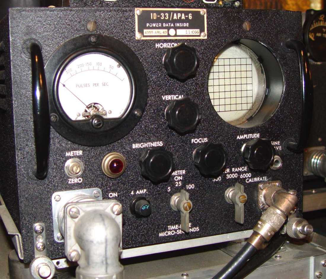
ID-33/APA-6 pulse analyzer
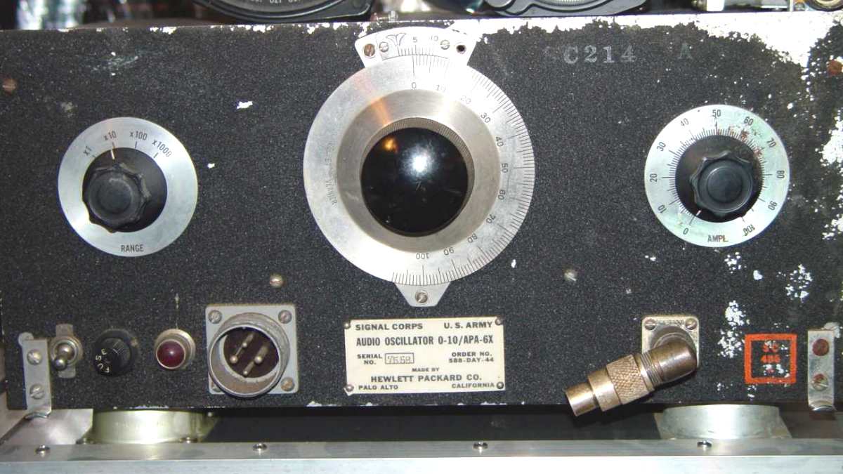
Hewlett-Packard O-10/APA-6X oscillator
It is tempting to simply consider the O-10 audio oscillator as simply a commercial H-P 200C with black wrinkle paint and military connector, but besides
the external structural changes that were indeed made to a number of commercial products early in 1942 (like the thumbscrew catches seen in the photo above), the O-10 had more
detailed changes in the circuitry, mentioned below. Another change was in actually designing and nomenclaturing an aircraft
shock mount for the oscillator, MT-197/APA-6X (note the "X" suffix on this, as well.)
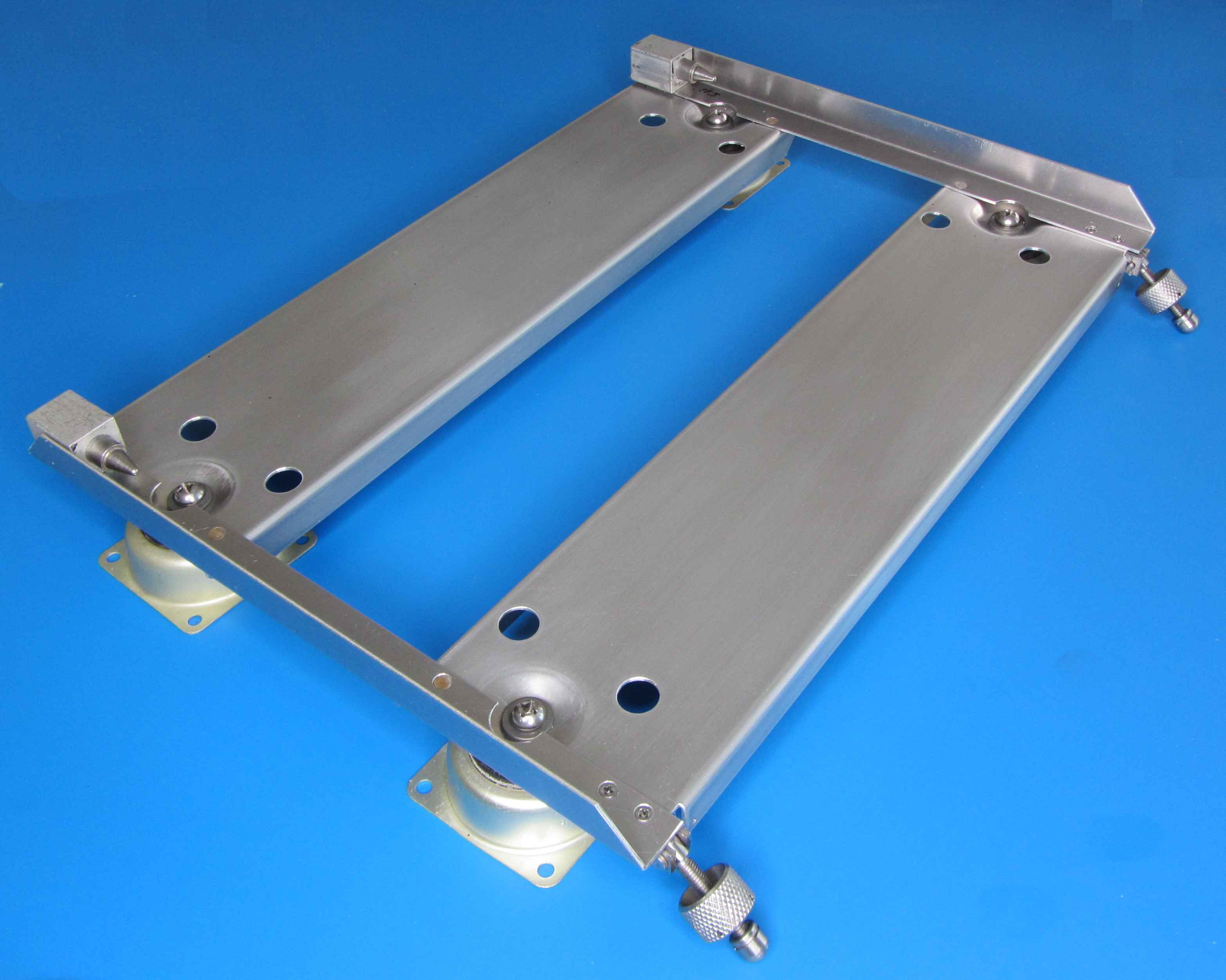
MT-197/APA-6X shock mount for the O-10 oscillator
I've finally had a chance to carefully trace out the oscillator wiring and modified what originally was the 200C schematic to reflect the as-built condition of serial number 7558 oscillator above.
One obvious change was to swap the 6V6 output tube in favor of a metal 6AC7. That makes sense, as the load of an oscilloscope in the APA-6X pulse analyzer presented a
high impedance, stationary load that did not need the power available from the original lab oscillator. Another is the substitution of another of the large rectangular non-polarized
capacitors (dual 4uF-4uF connected in parallel) as a coupling capacitor between the two tube oscillator secion and the straight amplifier section on the right half of the schematic. This replaced a
conventional three section aluminum electrolytic in the commercial 200C.
These capacitors, made by a California company by the name of Girard-Hopkins, are a curious throwback to prewar technology. A photo of the underside of the chassis showing them
is below the schematic. Besides being fairly large for their capacitance, they are made using a borate electrolytic, a popular capacitor dielectric in the 1930s. Being non-polarized, it doesn't matter which
way you connect them. I can see using one as a coupling capacitor because of low ESR perhaps, but a curious thing here is HP's primary use of them as B+ supply filter capacitors.
In the final model of the series, the 200D, there is only one used - a 4uF 800v unit for the power supply. I was amazed when I
measured lthem using first a capacitor checker with a DC voltage control (ZM-11) and then a DE5000 digital meter. All three measured slightly more than lable
capacitance, very low leakage current, and ESRs in the low single digits! This, despite one of them seeping a small amount of borate on the edge of the waxed cardboard sleeve.
Not bad for 75 uear old capacitors.
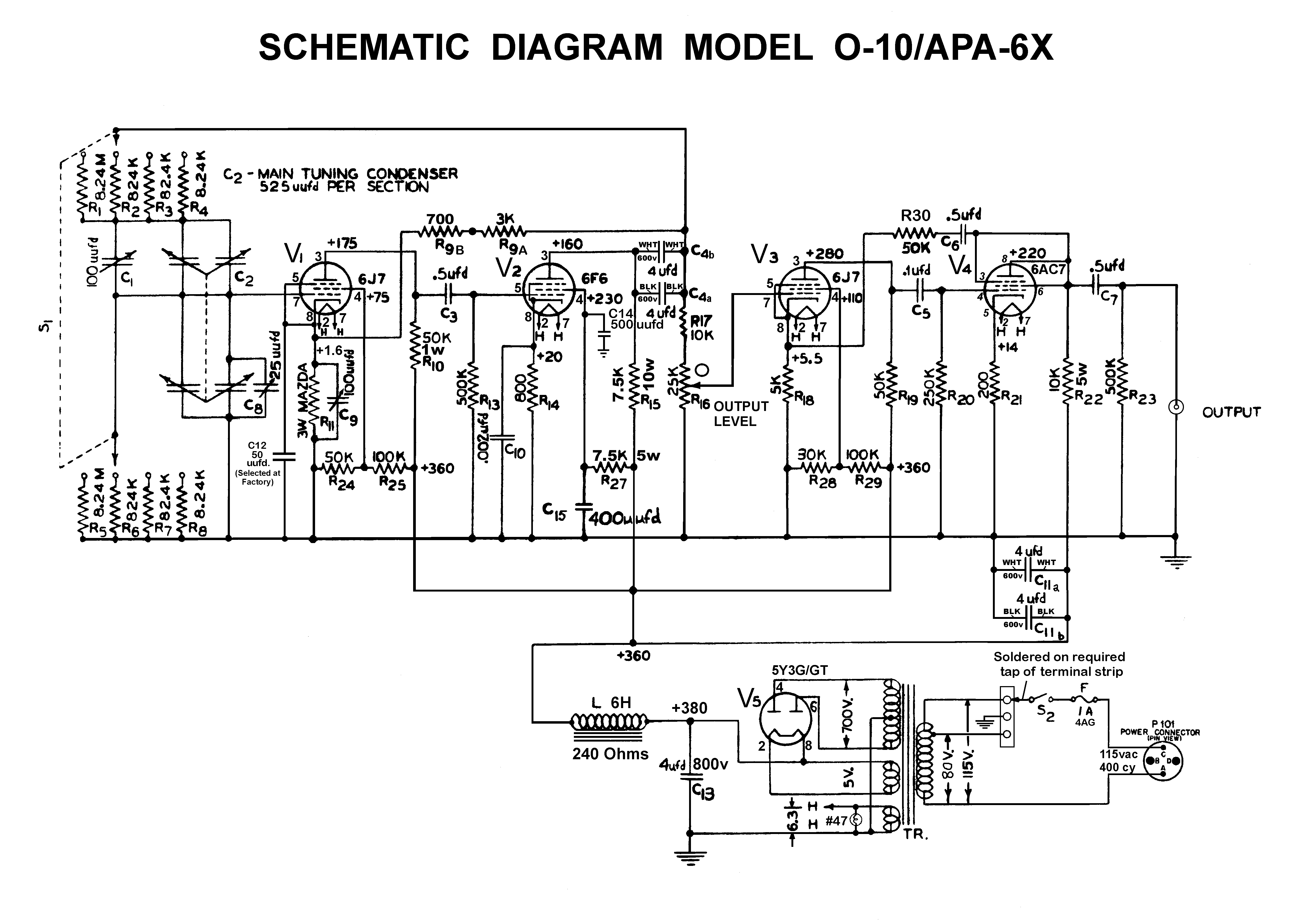
O-10/APA-6X oscillator schematic
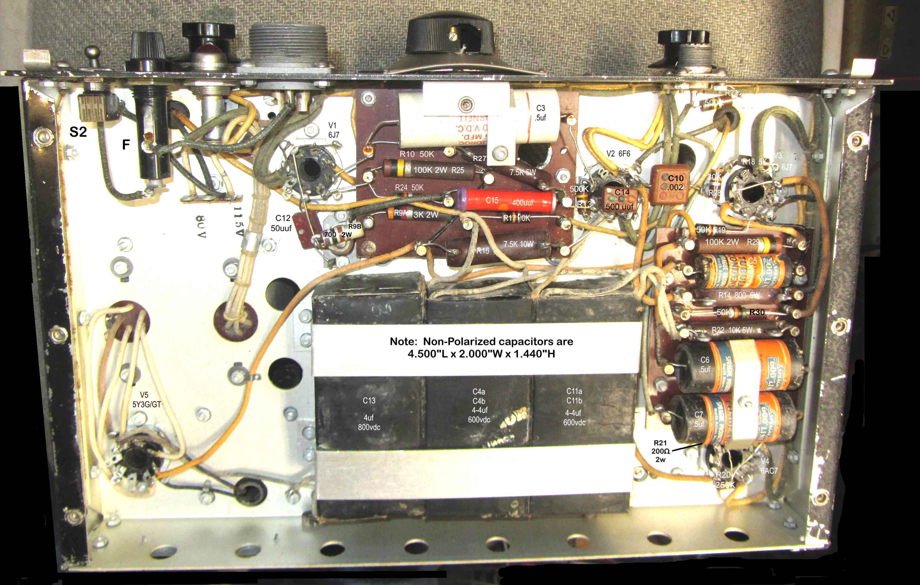
O-10/APA-6X oscillator bottom view
There are some Interesting puzzles in this view. C15 (the bright red dogbone ceramic above) is shown in the commercial 200C manual as a variable. In this apparently transitional piece,
they opted to include a 500pF parallel mica capacitor (C14), presumably individually selected for each unit. In the commercial successor 200D, it's apparently a
selected 400pF mica cap (C8 in the schematic and photo of the bottom of the unit, but of course has no value in the parts list.)
There is also a mixture of older stock "long john" 2W resistors and more modern Ohmite 1/2W resistors without any clear sense of what drove the older resistor use. There was a war on, I guess.
To be continued as priorities and time permit...
Return to Radar Countermeasures Page