Disaster Zone

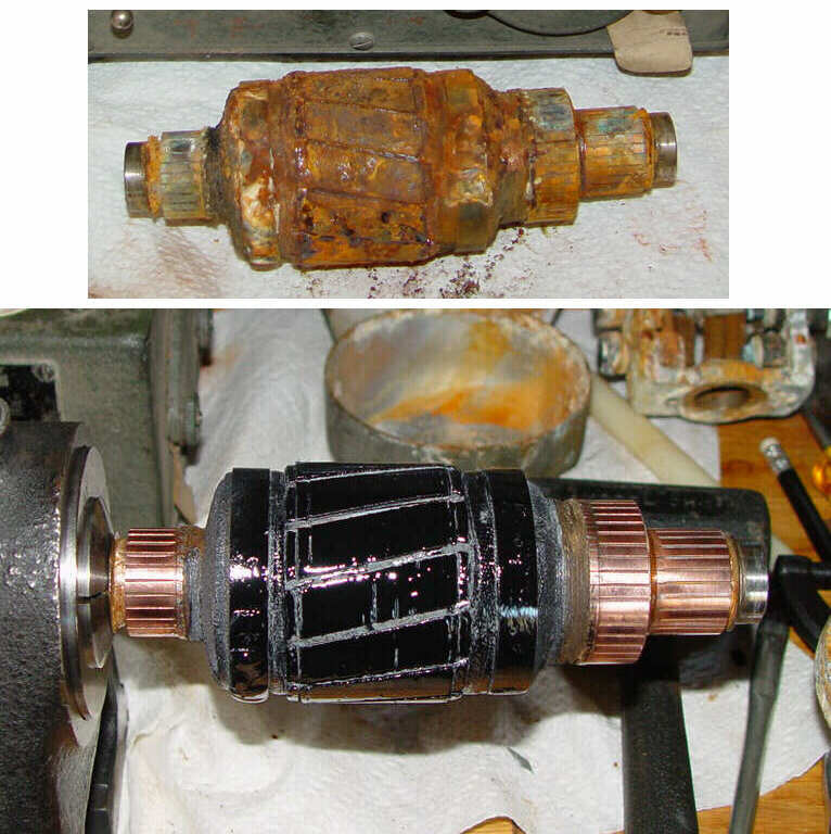
Before and after photos of the armature
After 60 years in a barn, restoration of just about anything to working order can be somewhat problematical,
but this poor old thing can give you an idea of what is possible. Stored in a moist
environment, the wrinkle painted exterior of this rare 1941 dynamotor (for a Marine Corps TBO and TBX) was
in surprisingly nice shape. Removal of the end bell showed a remarkably different story
inside, however. Items stored in sheds and the like are subject to extremes of temperature during a 24 hour
period, and this cycle causes “breathing” of an otherwise enclosed object, even
if it is in a box or under a tarp. This breathing action brings in moist air, which then condenses on the
interior during the coolest part of the day. You can see what results from that phenomenon in
the top picture. The well known Bendix “football” direction finders that were installed on
larger WWII aircraft used a silica gel dehydration tube connected to the loop enclosure with
flexible tubing to combat this problem.
Dynamotors with multiple windings like this one are uncommon enough to warrant unusual amounts of work to
bring them back. This one has voltage outputs of 3vdc and 150vdc, not your every day single
supply voltage. Simply getting the armature out was an exercise in extreme patience, not to mention the
next series of tasks in the queue, like cleaning and restoring the end bearing frames and pole
pieces. Luckily for this particular armature, one dynamotor end bell was still loose enough to get off
without cutting into anything, allowing the following sequence to be used:
1) Remove brush caps and brushes from bearing frame.
2) Remove screws holding wires and capacitors to the brush assemblies. Note - the insulation on wiring
subjected to this kind of moisture is extremely fragile, and will flake off in a heartbeat if
the wire is bent or otherwise manhandled. If that occurs, then you have two choices – replace or
repair with heat shrink tubing. Keep track of where all the capacitors and wires go with photos
or sketches.
3) Remove two nuts holding the bearing end frame, then use a small dead blow hammer to loosen the frame
from the body of the dynamotor. It may be necessary to use a screwdriver as a wedge to keep the
long studs from turning. It should be possible to slide the end frame off of the body at that point,
carefully threading the wires between any obstructions.
4) With the end frame off, it should be possible to wiggle the armature out of its home. If it requires
mechanical force, the only location you can grab it with any force is the end bearing.
Do not try to grab the commutator with a tool – it’s extremely fragile.
5) With the armature out of the case, you will need to temporarily reinstall the bearing frame and
retaining nuts. The reason for this is that the other dynamotor end bell is usually impossible
to get off easily. (You did pick the easiest end to remove first, didn’t you?) If you try to
bump off the end without restraining the end frame, it will be difficult to grab when/if it
comes off with the end bell still attached. That will leave you with an end bell on the end frame and back
in the same situation as when you started.
6) Using a nylon or soft pine dowel, begin tapping through the dynamotor on the end bell from inside. Using
a plastic hammer around the junction of the end bell and the bearing frame will also
help break loose the corrosion that is holding it. Be aware that it is extremely easy to tap on the
unsupported part of the bell and dent it unless you are careful. I have some excellent examples to show you
if you doubt this advice...
7) It is almost impossible to keep dents from forming in the end bell during this process unless you are
very lucky. Steady tapping in a variety of places is better than wailing away in one spot with
a five pound hammer, but expect a few bulges after you finally get it off. Fortunately, those will respond
nicely to the large end of a small ball peen hammer and some careful bumping.
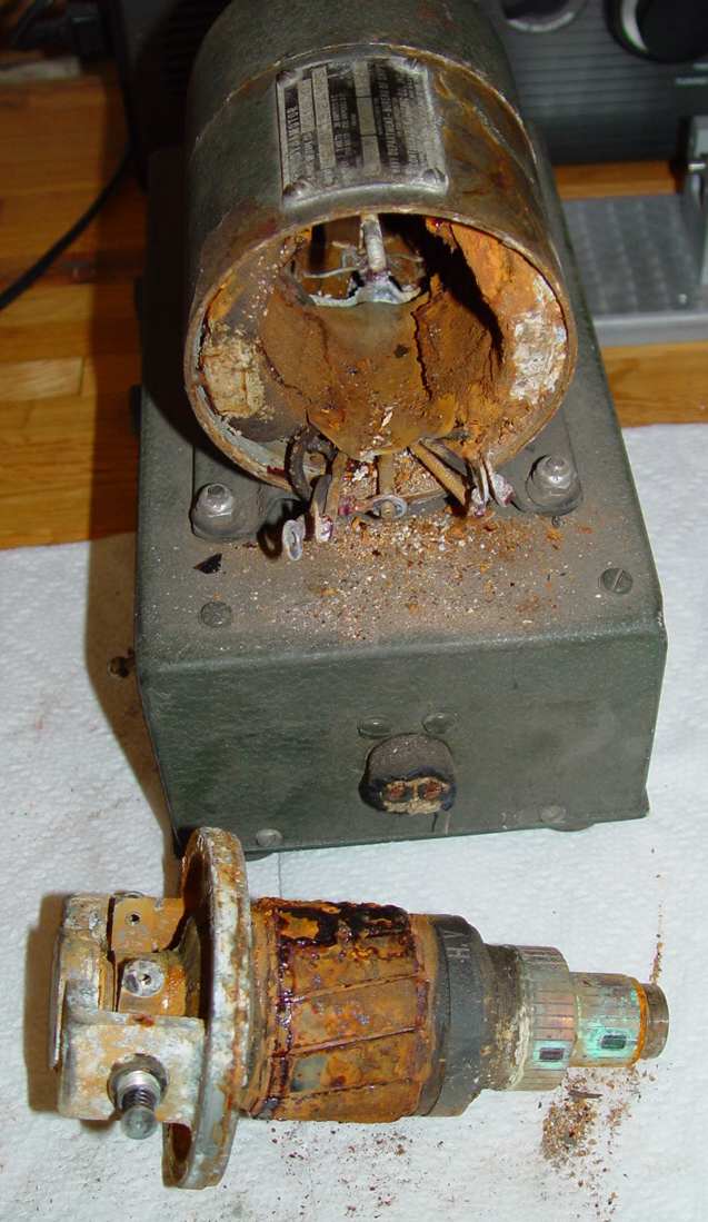
8) Remove the two end frames at this point. This will leave the pole pieces and the stator windings in the
dynamotor shell. Here it how it looked at this point:

9) Removing the pole pieces will finish off the disassembly process, but be very circumspect about removing them.
The reason for caution is that they are bored in place after assembly to a +.002"/-.005" concentricity tolerance,
with respect to the frame O.D., and are held on (usually by staked
screws) in a very determined manner. If removed, it's a good idea to use an expanding mandrel to get them aligned
properly again. If you have determined that it is absolutely necessary, the easiest way to get the screws out is with a
3/8" impact driver, which is an inexpensive tool that you insert into the screw slot and strike with
a large rubber or plastic hammer. This not only shocks any corrosion retaining the screw, but seats the
blade in the screw slot and twists at the moment of striking, combining the best techniques possible for
removing a recalcitrant fastener. You do NOT want to grab the dynamotor body in a vise to do
this, however. It is necessary to put a cylindrical anvil inside the body (okay...a big pipe held in a
vise) to keep the thin body from collapsing when you hammer on the driving tool.
10) Getting the bearings off of the armature was an exercise in itself. They did not succumb to the usual
persuasion of either a small bearing puller with fingers ground to a knife edge, nor an old
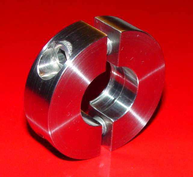
collet in the indexing fixture seen above. I eventually made a special bearing puller with a thin ridge to grab the back of
the bearing, shown below.

Bearing puller
11) With it all apart, restoration can finally begin.
To be continued sometime in this century
Return to AAFRadio

