The desperate months...
Early 1942 found the US in a sad situation, both from a strategic standpoint and from the standpoint of
advanced tools required to be effective on the battlefield. Most of the equipment that they possessed was from the
1930s, and technology was rapidly passing us by. Because of the need to understand the electronic threat
against us, we followed the example of the British - who after all had been doing it for two years - and
pressed into service what we had. This bay shows the basics of that capability, reflecting a photograph
of an installation in an early Pacific theater B-24 ferret aircraft of the time, shown below:
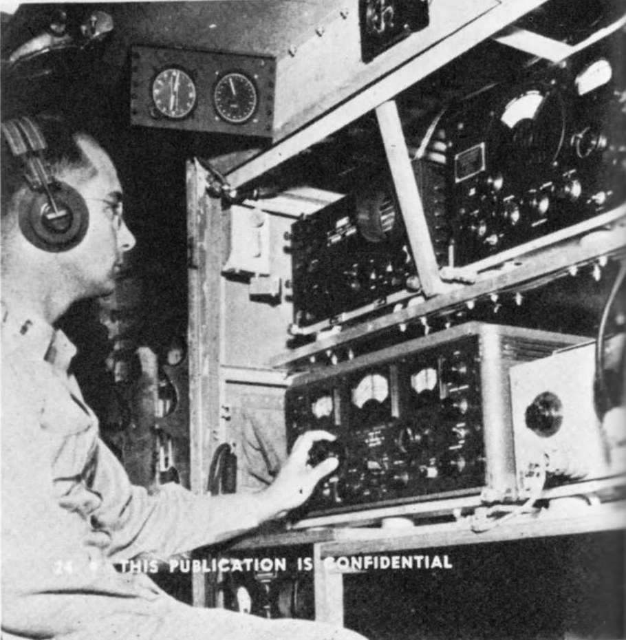 Early signal collection equipment. This included a BC-1031 or BC-1032 panadapter, Hallicrafters S-27
and SX-28 receivers, and a rudimentary pulse analysis capability formed through the use of a 1930's Dumont "oscillograph" and an HP audio oscillator.
Early signal collection equipment. This included a BC-1031 or BC-1032 panadapter, Hallicrafters S-27
and SX-28 receivers, and a rudimentary pulse analysis capability formed through the use of a 1930's Dumont "oscillograph" and an HP audio oscillator.
Above the operator's head in this photo is a magnetic compass repeater indicator on the left, driven by the flux gate compass in the wing of
the aircraft. To its right is a slave indicator that provided directional information from the AN/APA-24 rotatable Yagi
antenna that was mounted outside the fuselage. By correlating data from the two, the operator could determine the direction
of a target signal received on the Hallicrafters S-27 VHF receiver mounted to the far top right in front of the operator.
The panoramic adapter to the left of the S-27 is a BC-1031 with a 455kHz IF input, judging from the gaze of the operator and
his tuning of the Hallicrafters SX-28 beneath the BC-1031. Alternatively, an outwardly identical BC-1032 was carried whenever some a form of
spectrum visualization was needed for the S-27 scanning. To the right of the SX-28 is a portion of a Hewlett Packard 200B audio oscillator,
used with a Dumont 224A 3" oscilloscope (not seen in this photo) for accurate radar pulse repetition rate determination.
The shock mounts for all the pieces above were custom made. They used the model of the ARINC 404 specification, except they had to be widened and shortened
on an individual basis for each piece of commercial equipment. Note the set of six shock mount elements under the S-27 and SX-28...these buggers are heavy!
All of the later military repackaging of this equipment used the ATR (Austin Trumbull Radio)
portion of the specification, modified by the military to their own peculiar system. The standard "single ATR" became the "B1-D1" size in milspeak.
Countermeasures equipment embraced this model almost exclusively from the start, probably because it was realized quite early that equipment was going to
require rapid insertion and deinstallation for each mission.
At upper left in the photo below is an audio oscillator that was used to characterize pulse repetition rates. Initially this
Hewlett Packard oscillator was bought and used in the original gray wrinkle finish version of the HP 200-A seen above, but as time went on, a specialized
model was produced that had the regulation black wrinkle finish, in addition to being shock mounted and cabled specifically for countermeasures work - the
rare O-10/APA-6 shown below. At the far right is the Dumont 224-A oscilloscope used to display Lissajous figures, using the receiver output
and the oscillator output as x and y inputs. Comparing the number of lobes on the Lissajous trace with the frequency indication on the oscillator
would reveal the pulse repetition rate to a fair degree of accuracy. The box in between is a Navy RL-7 interphone amplifier awaiting disposition to a more
suitable location in the "flight deck."
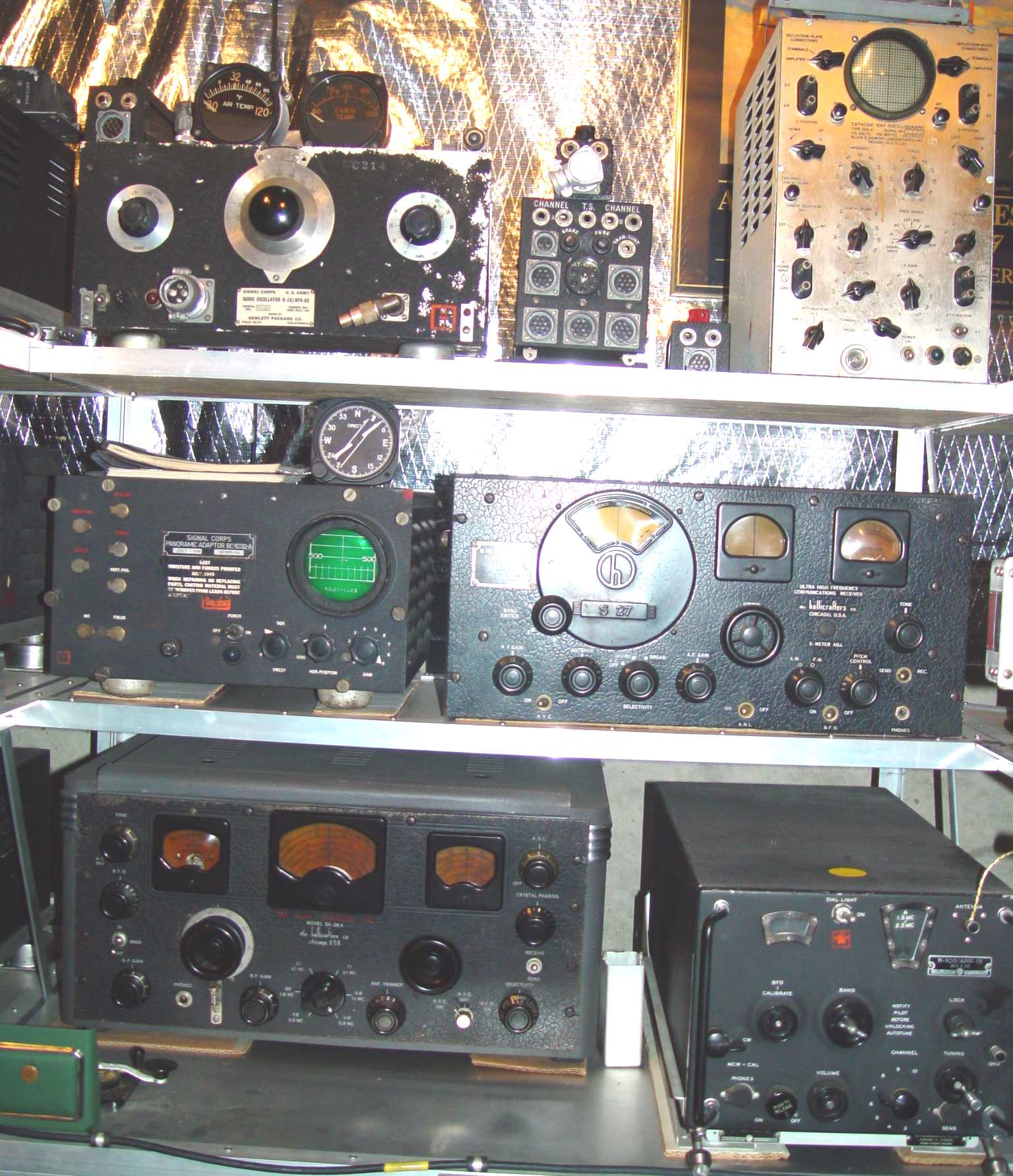 Early signal collection equipment in a modern setting. (The AN/ARR-15 receiver at lower right is not a part of the early ECM gear - it just fits
conveniently there next to an AN/ART-13 transmitter unseen in the rack to its right.)
Early signal collection equipment in a modern setting. (The AN/ARR-15 receiver at lower right is not a part of the early ECM gear - it just fits
conveniently there next to an AN/ART-13 transmitter unseen in the rack to its right.)
On the next shelf down is a BC-1032 panoramic adapter, designed to be used with the Hallicrafters S-27/S-36 receiver
to its right. This particular receiver was labeled an S-36M, the modification being an SO-239 connector on
the left side of the set to feed the panadapter. It is unusual in another sense as well - for a brief period
Hallicrafters had reportedly not had time to stamp a tuning dial faceplate with the new S-36 designation on it, so
this one and a limited number of others had the new circuitry and the old S-27 faceplate.
Both the S-27 and SX-28 receivers were reworked and repackaged
into ATR aircraft configurations as the AN/ARR-5 and AN/ARR-7 shown here .
Hallicrafters took the opportunity to introduce some minor circuit improvements in these sets, which showed up in the S-36 and SX-28A. They also were required
to install an extra RF stage to reduce local oscillator bleed-through to the antenna, but the execution of this specification was sadly lacking and mostly just
introduced additional broadband noise at the expense of the perceived detection prevention. An unauthorized mica capacitor jumper between grid and plate pins of the
isolation tube (with removal of the tube) improved things tremendously...heh.
Return to AAFRadio