APA-17 Direction Finder
This unit was a replacement for the earlier labor intensive procedure of using a manually steered dipole antenna (APA-24)
and a pad of paper to record signal strengths from a suspect radar, as the ferret aircraft flew past just beyond the
edge of detection.

The display unit above was the heart of the DF unit, allowing a radar-like display of signal strength versus compass heading.
It was accompanied by the PP-85 power supply below, and a rotating antenna assembly shown below that.
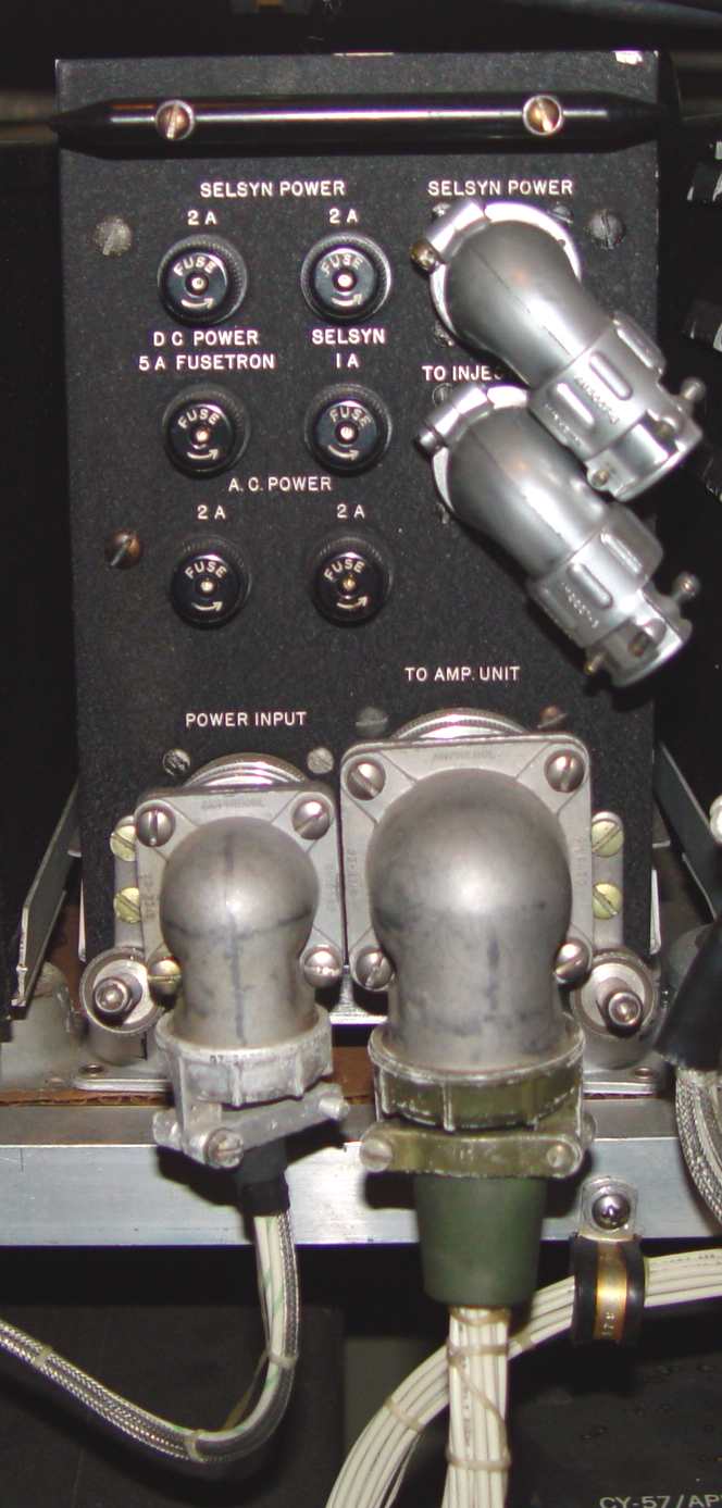
PP-85 power supply

AS-108/APA-17 rotating antenna for the DF set - one of several available for different frequencies. A radome was
installed over the top to keep the weather and slip stream out. This view shows the horizonatally polarized dipole antenna
elements.

View of the vertically polarized monopole.

Drive assembly. This incorporated a solid silver rotating joint that maintained VSWR at 50 ohms throughout the feed assembly.
Return to AAFRadio