The German V2 jammer
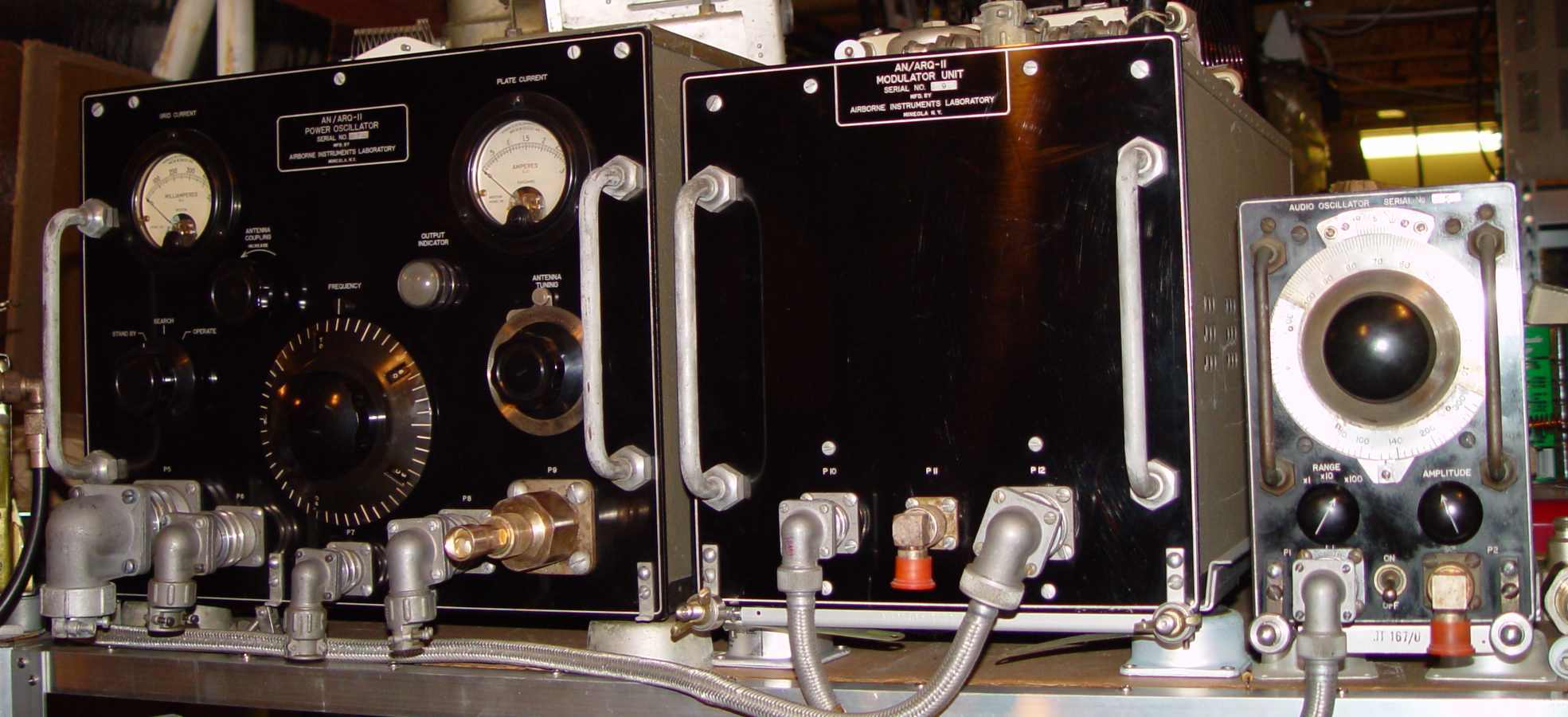
The three primary transmitter units - power oscillator, modulator, and audio oscillator
In 1944 the threat of the German Vergeltungswaffen weapons caused a great deal of
activity in electronic countermeasures work. Initial signals collection around
Peenemunde showed some unusual emanations in the 20-70MHz area, and it was surmised that the
V2 was guided by this frequency. Subsequent analysis could detect nothing in
that band of frequencies when the weapons began falling on London and the English
countryside, further deepening the mystery. As it turned out, postwar accounts
indicated that early surveillance intercepts were most likely a tracking system developed by a Professor Wolman, using
triangulation from multiple sites around the V2 launch site, and of course no one on the Allied side knew it was initially guided by
an on-board gyro and vanes in the exhaust stream and then became a straight ballistic package. Later in its use, a radio guidance
system was in fact introduced to improve accuracy (Lorenz Leitstrahlstellung), apparently working around at a frequency around
45MHz and installed on the last 25% of V-2s produced. Its effectiveness was not completely clear, given that the guidance system
only worked during the powered portion of the missile's flight. Since there was a huge amount of Allied electronic surveillance work
being done by 1944, interception of even these short transmissions may have had a part in the race to develop countermeasures.
At any rate, the British began deploying a ground based jammer with about 75KW output to counter the perceived threat,
and used highly directional antennas to point toward Peenemunde. Thinking ahead, the
Americans were concerned about what happened if and when the V2 show went on the road...the
Germans had already proved to be masters of mobile weaponry. In any event, the ARQ-11 was the initial product
of a well known EW company by the name of Airborne Instruments Laboratory (now AIL Technical Services Operations, currently a business
unit of EDO). The jamming system was quickly built and tested in a B-24 during the summer of 1944. It
used a pair of British "micropup" radar pulse triodes in a push pull power
oscillator configuration to get 1,700 watts output at the lowest frequency point of 20MHz. The
need to get such power out of tubes designed for pulse applications required a huge "canister vacuum
cleaner" blower of the type pioneered by Electrolux at the rear of each valve, simply to obtain any life out the tubes at all.
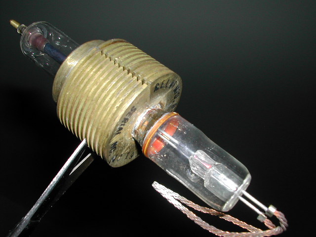
One of the REL-1 micropup tubes
The power oscillator was a tuned push-pull oscillator with no further amplification, pictured below.
Note the plate current meter,which reads the combined plate current from the 6kV supplies - 3 amperes full scale!
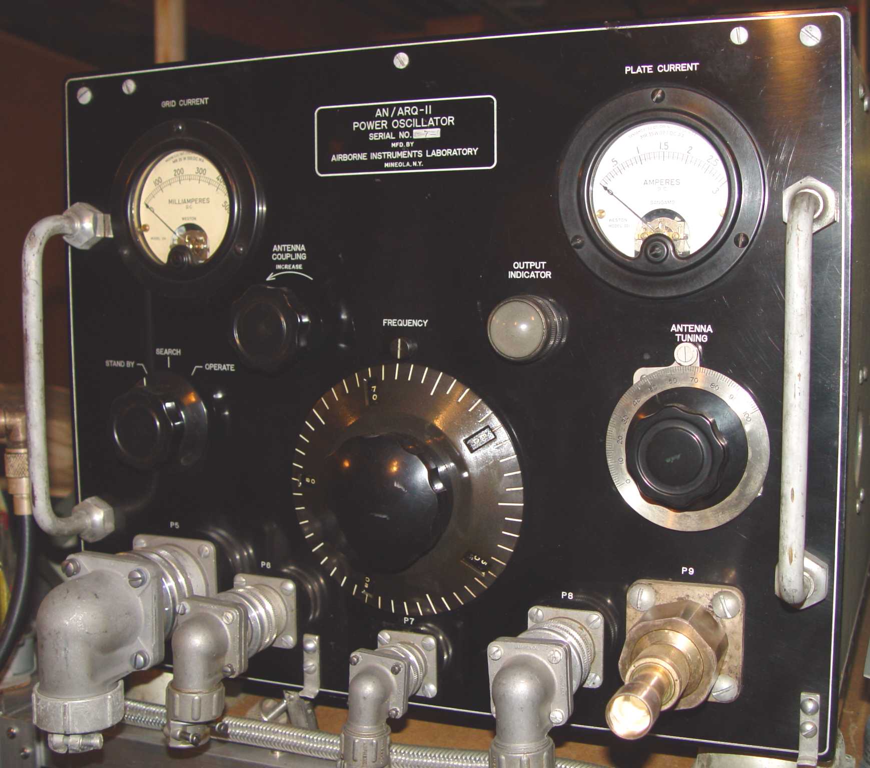
T-102/ARQ-11 power oscillator
It's probably a miracle that this set has survived - it has numerous parts in it that radio amateurs used after the war
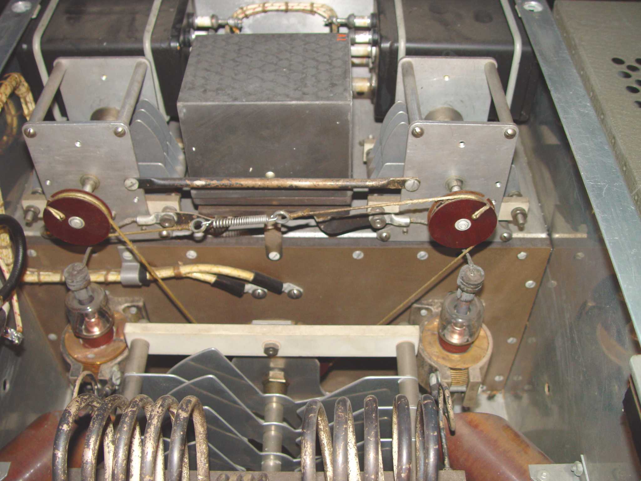
to make kilowatt rigs. Below are shown some details of its exquisite construction.
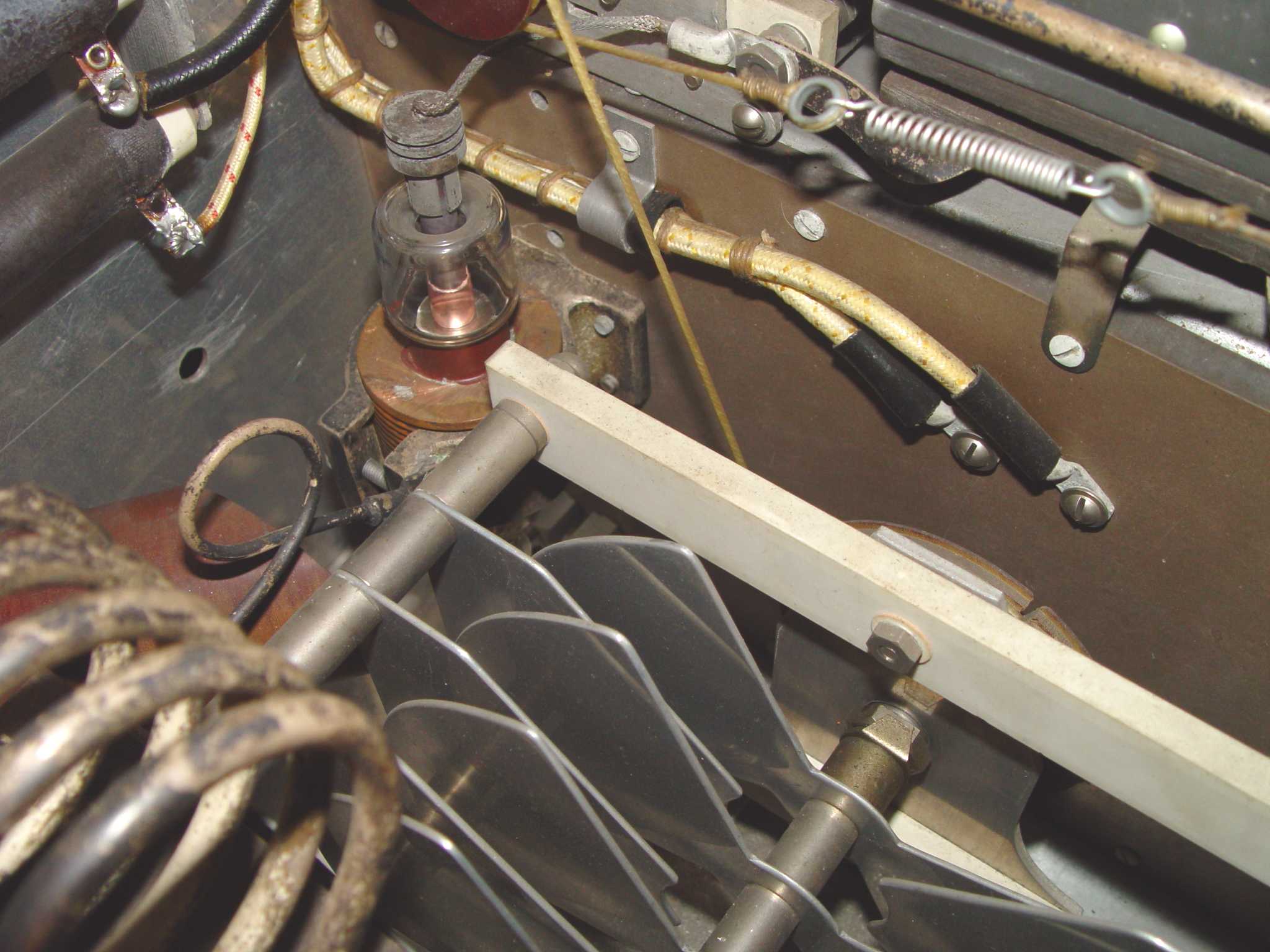
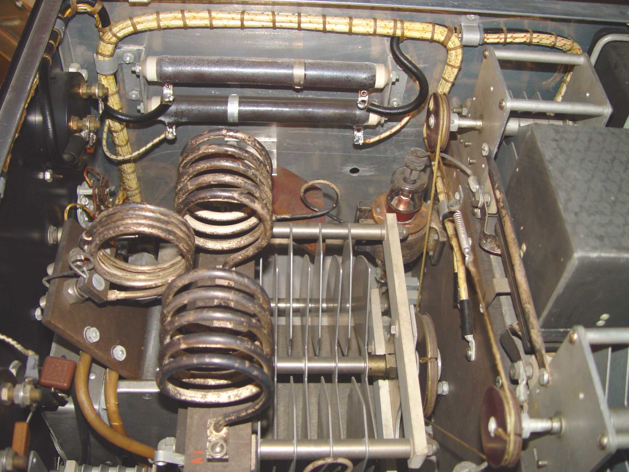
This view shows the plate coils and swinging link. Five sets of these coils were required to cover 20-70MHz.
The modulator is designed to provide the proper grid excitation for the three modes of operation shown on the
transmitter panel, and included a clipper stage, a 3MHz local oscillator, a full wave rectifier, an output keying stage,
and a power supply. The 30Hz to 30,000Hz sine wave oscillator input coming from the O-28/ARQ-11 is amplified and shaped
to a square wave, which is used to key the local oscillator. The output of that stage (a pair of 807 tetrodes) is rectified
and applied to the grids of the main 811 modulator tubes.
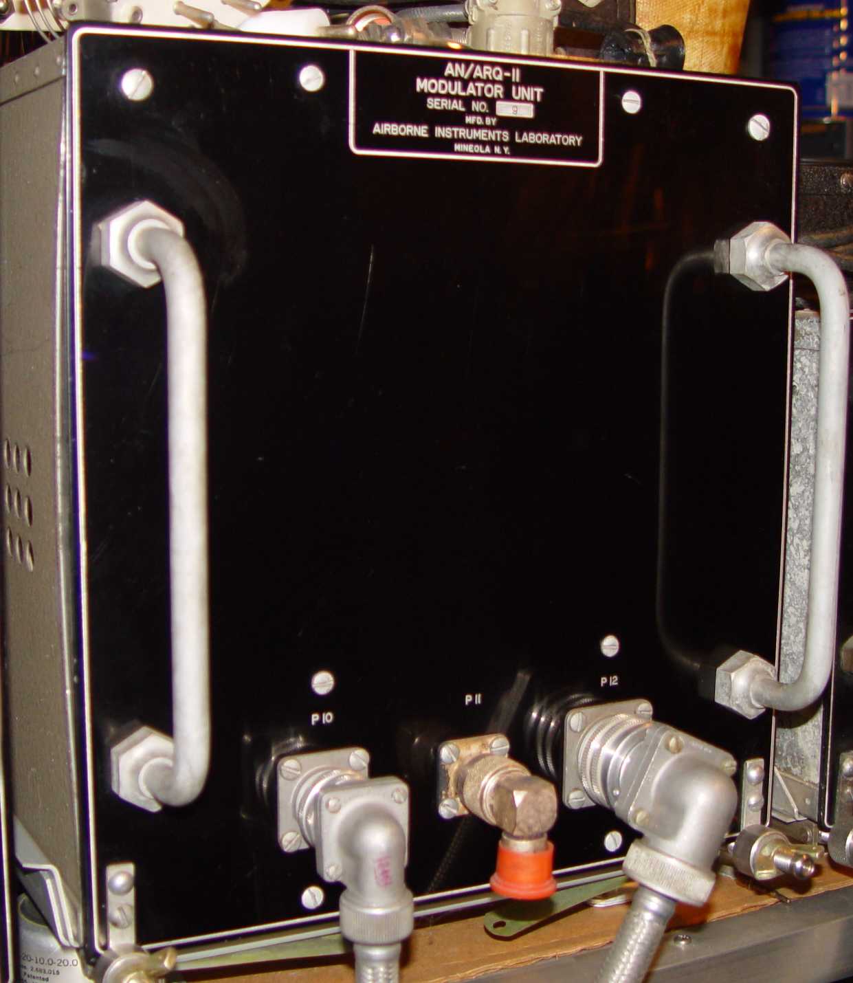
MD-42/ARQ-11 modulator
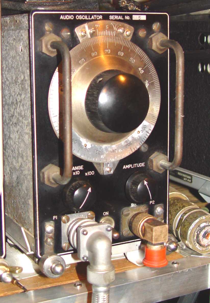
O-28/ARQ-11 audio oscillator
Three power supplies were used with three phase 400~ input to get the 6kV at 2 amperes needed for the transmitter.
Only about a dozen complete ARQ-11 sets were manufactured before the contract was terminated because of the pace of ground
advance in Europe. This particular power oscillator is serial number 9, the modulator is
serial number 6, and the audio oscillator is serial number 5. This set is missing
only the C-187/ARQ-11 junction box/power panel and the associated R-21/ARQ-11 receiver. If anyone has any documentation or
pieces of this set, I would deeply appreciate them contacting me.
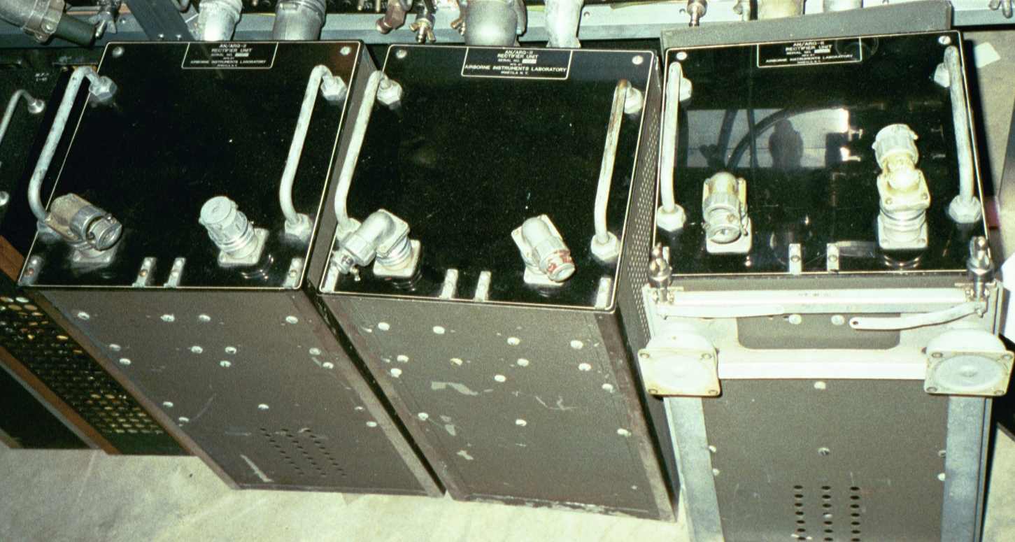
The three PP-130 power supplies
Return to AAFRadio


