B-29 Antenna Photos
Fuselage interface photos
The two insulators shown below were replacements for a more unwieldy approach that appears beside them. The original design
concept for the cockpit end of the ~74 foot long wire antennas was to lead them through a pair of molded phenolic insulators
that were mounted flush with the aircraft skin. A hole in the center of the oval insulator allowed the Copperweld steel cable
to enter the fuselage in the bomb bay area and be restrained by an internally mounted anchor. The rather frequent need to
replace antenna wires due to a variety of reasons made this approach very time consuming from a maintenance standpoint, and
was abandoned well before the end of the war. Its replacement was a simple ceramic feed-though insulator, streamlined per
Boeing sprecifications.

View of external portion of feed-through insulators. The streamlined one is from the aircraft's original construction, while the top one is a more conventional
feed-through that was used after the war.
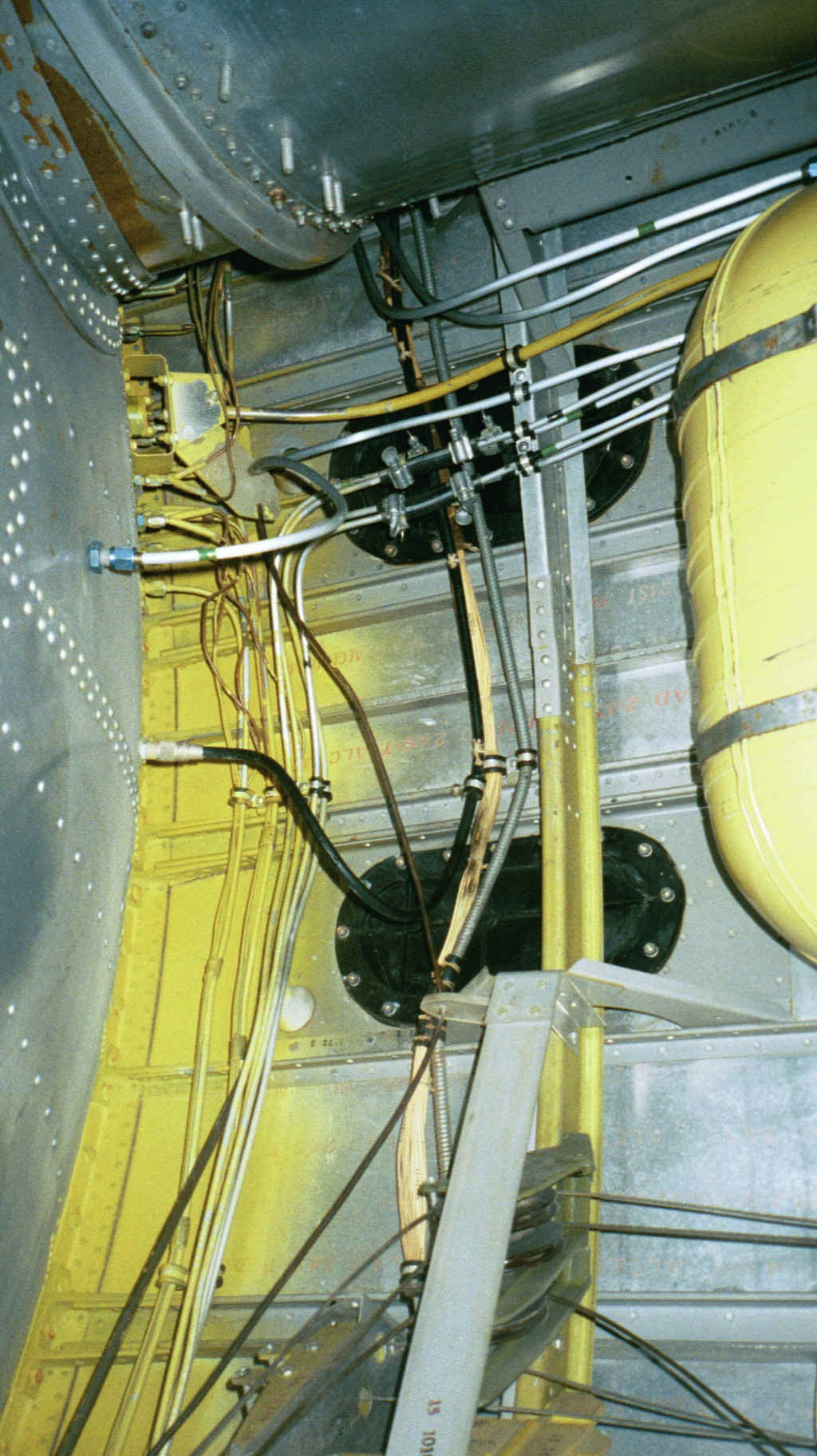
View of the upper portion of of feed-through insulators and connecting wire between the fuselage insulators and the pressure hull insulators, looking almost
vertically upward from the bomb bay. The antenna wire is standard unshielded aircraft spark plug wire inside flexible phenolic tubing, then heavily varnished.
AC Delco provided most of this kind of wire under the Packard 440 designation. Note the two 1/4" Plexiglas wire guides.
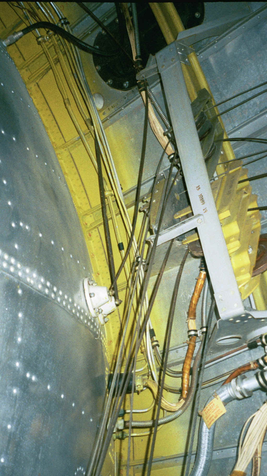
View of lower portion connecting wire between the fuselage insulators and the lower pressure hull insulators, again looking almost vertically upward from the
bomb bay. No other wire guides are visible.
********************************************************
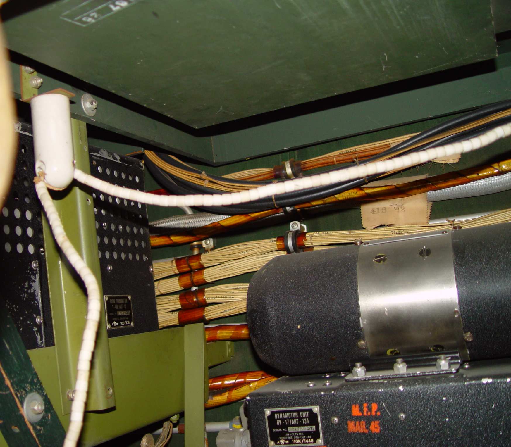
Routing of ART-13 antenna feeder within pressurized compartment
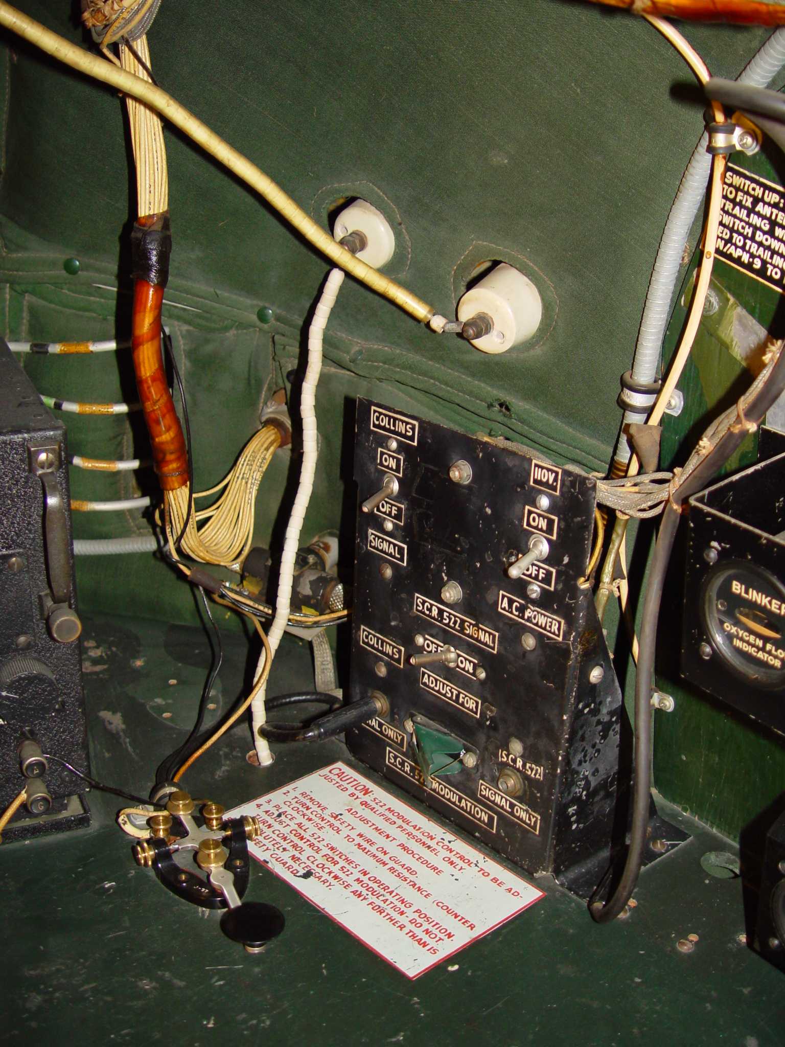
Interior view of entry point through the pressure hull of both liaison and command long wire antennas. Note that the ART-13 feeder simply
runs through a 5/8" hole in the radio operator's desk. The IN-83 insulator beads provide standoff of the
bare tinned wire to the plywood. The addition of the second ART-13 to all of the atomic "Silverplate" aircraft necessitated a run of insulated
beaded wire close to the original key position...thus the obvious relocation evidence seen above.
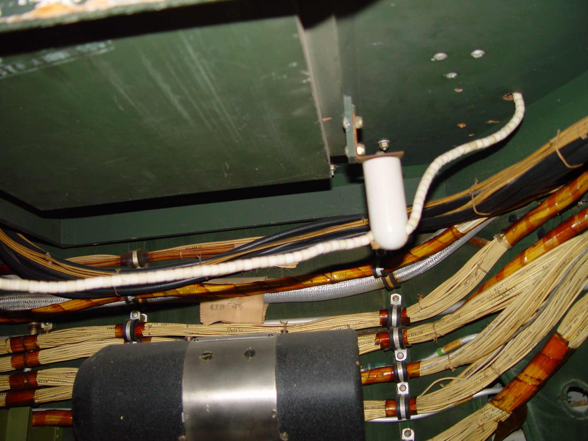
Views beneath the radio operator's desk, showing the routing of the ART-13 antenna wire through IN-82 insulators.
Return to Documents page