PB4Y-2 Line Mantenance Manual Excerpts
Cover sheet for the manual
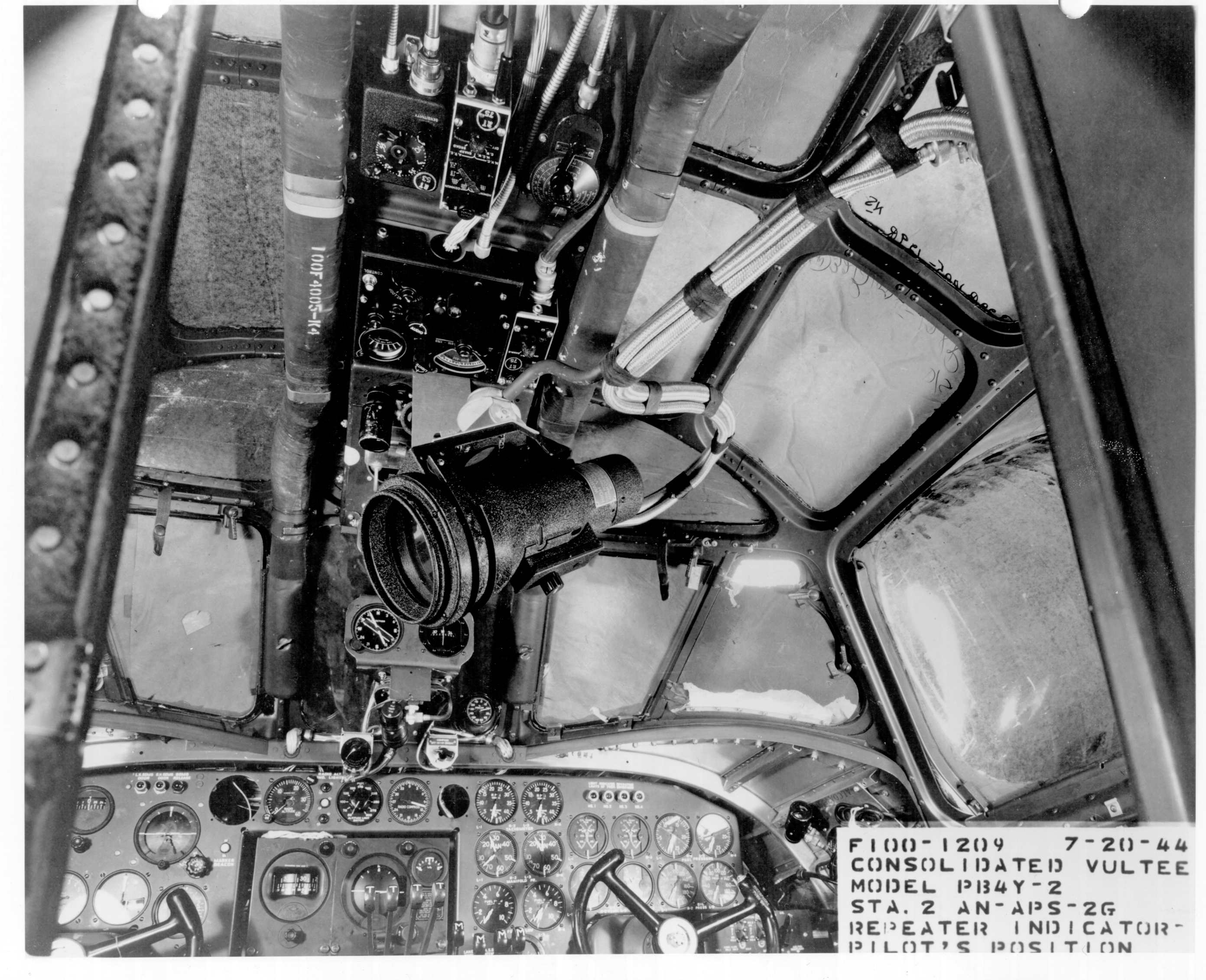 Pilot/copilot overhead details
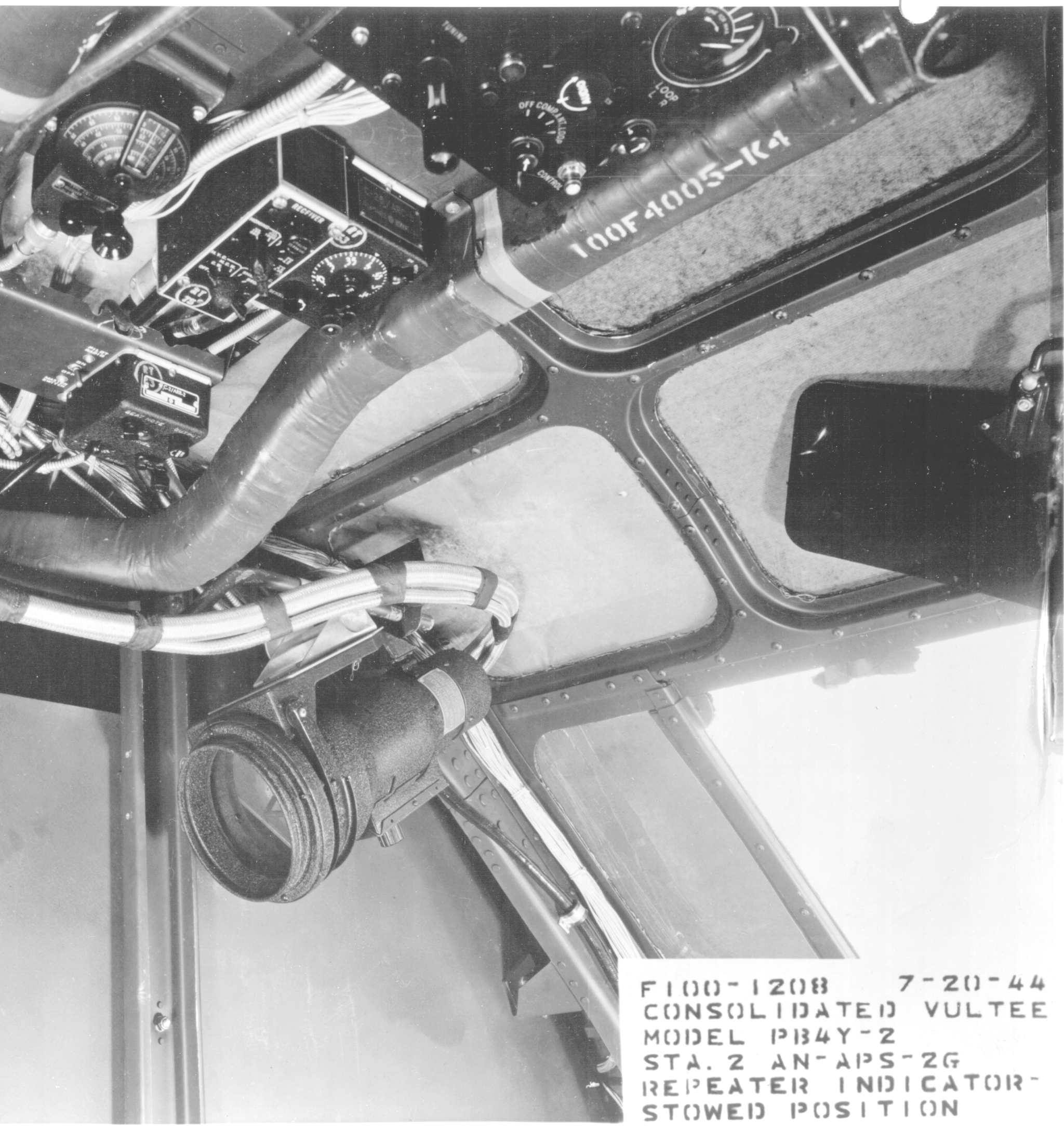 Above the copilot's position with the APS-2 slave indicator in the stowed position
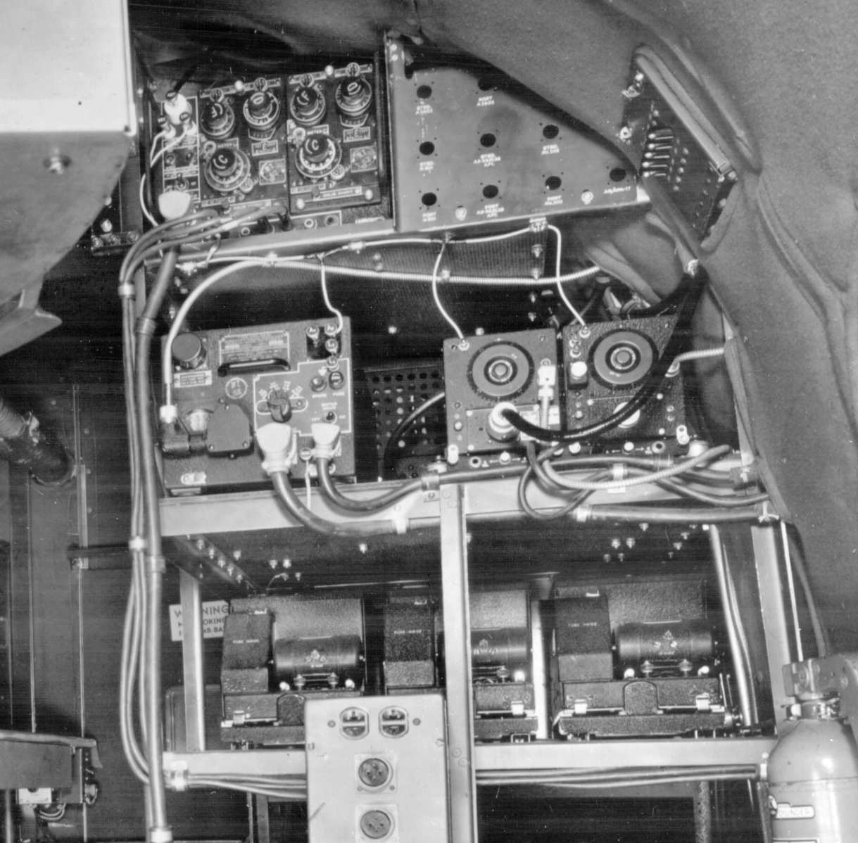
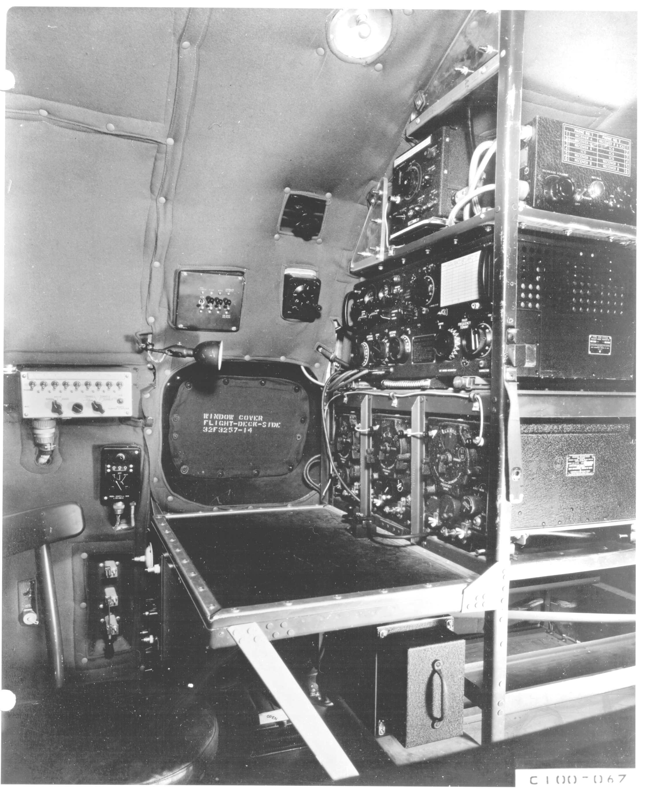 Radio operator's position. Actually, this was a ferret aircraft, so the radio op more likely doubled as the HF
intercept officer as well.
Radio operator's position. Actually, this was a ferret aircraft, so the radio op more likely doubled as the HF
intercept officer as well.
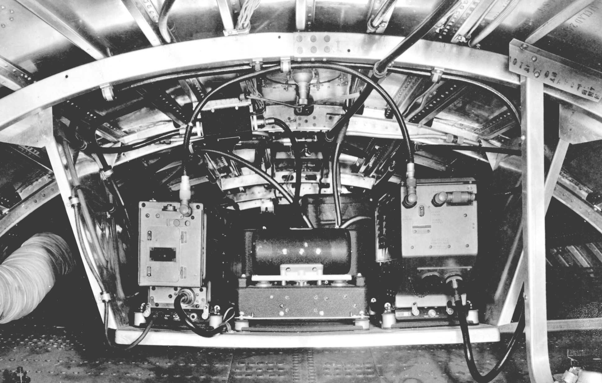
 Rear of the HF operator's bay, which faces the ECM collection area. Antenna patch connectors and other cabling have yet to be installed at this point in time.
 Proof positive that VHF was king in 1944! (Being facetious, of course.)
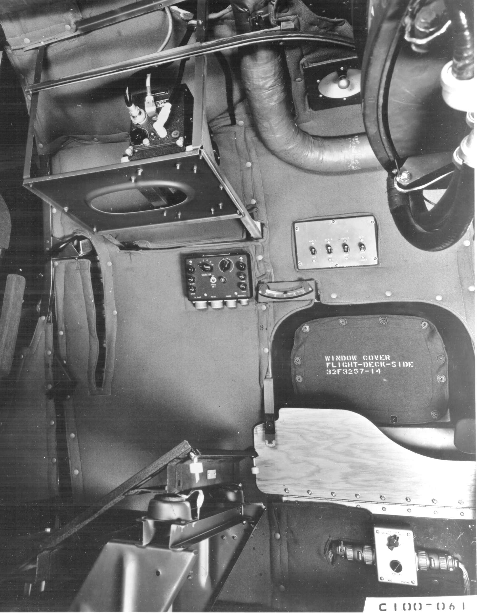 AN/ARR-2 VHF homing receiver mounted above the APS-2 operator's position.
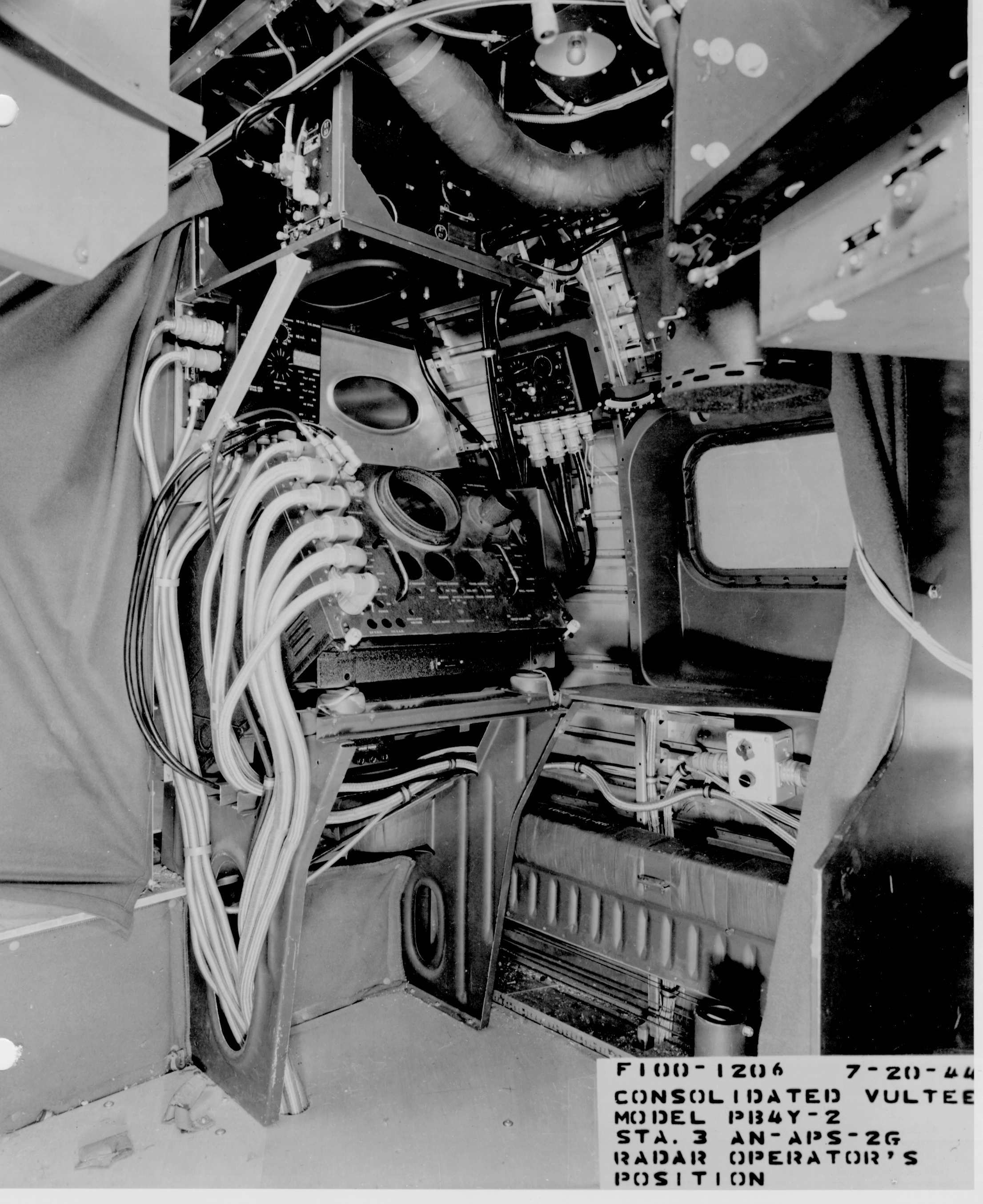 Somewhat later view of the APS-2 installation. Note the use of an empty display shell to get cable lengths correct during installation.
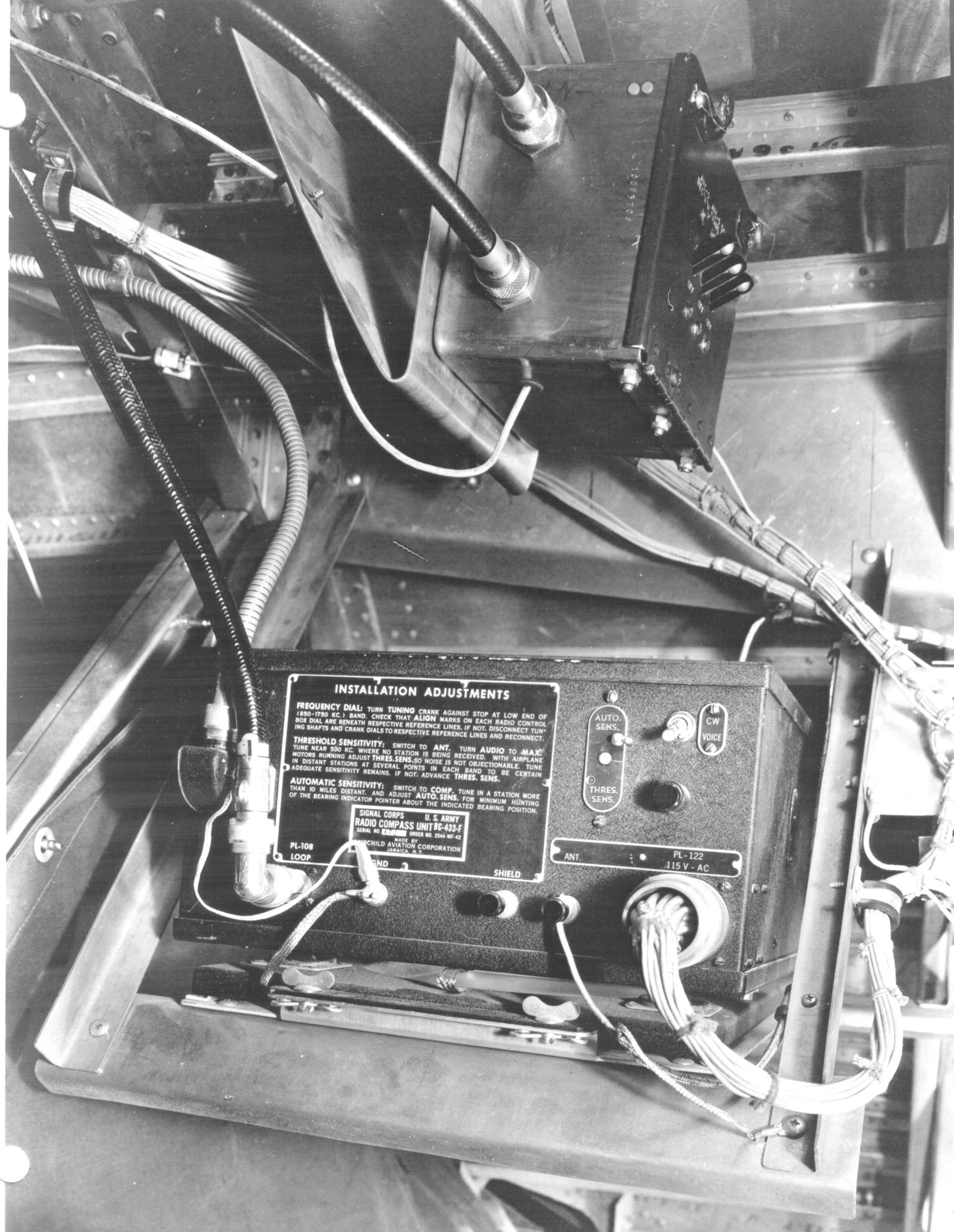 SCR-269 radio compass - a Signal Corps piece of equipment in a Navy aircraft! The Navy seems to have adopted the USAAF "quick and dirty"
open wiring approach to connector backshells, abandoning their traditional exquisite vinyl or braided copper covered flex tubing
(at least for this one piece of equipment.)
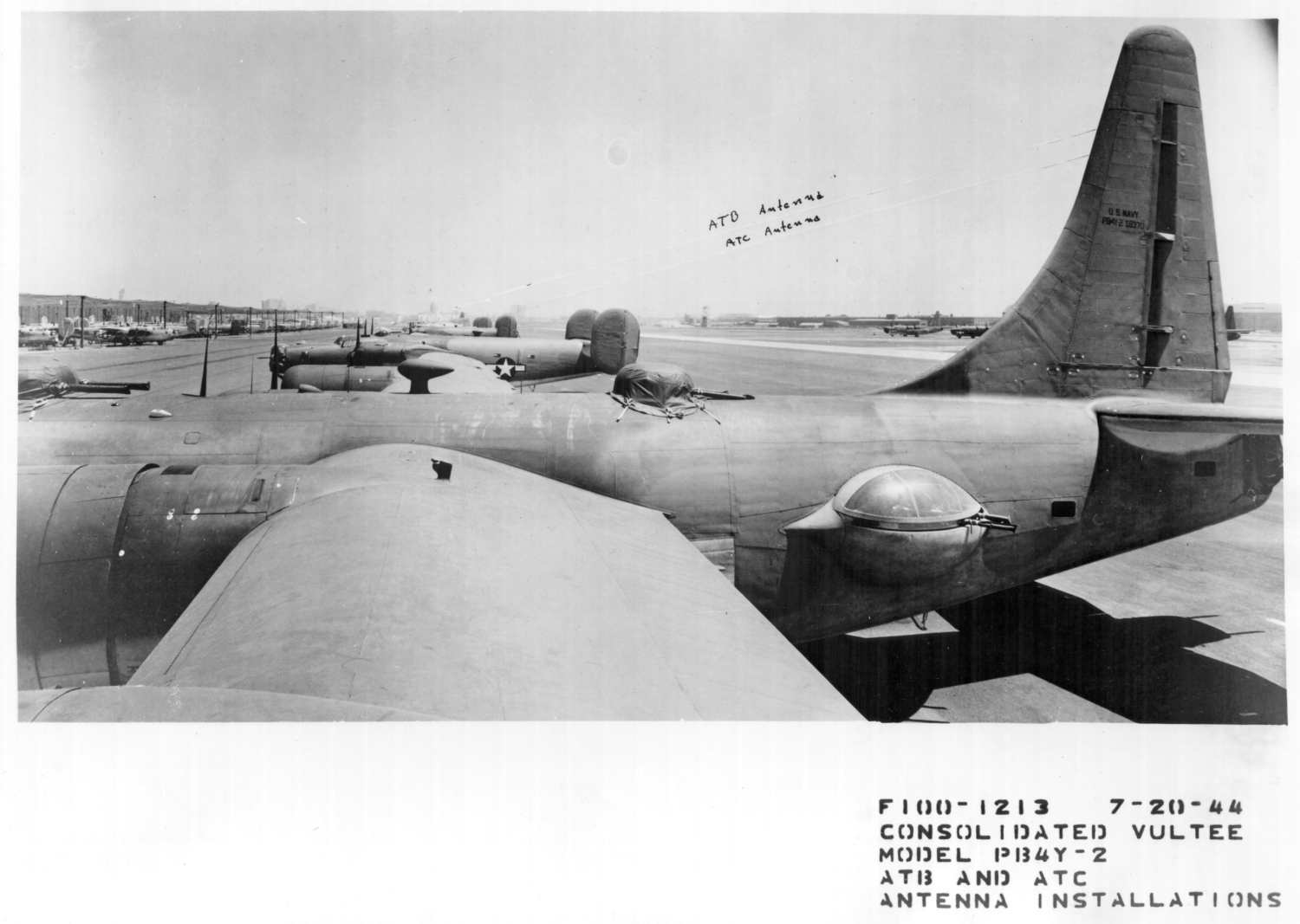 A series of photos of the antennas installed on this ferret aircraft. This one shows the ATB and ATC antenna installation.
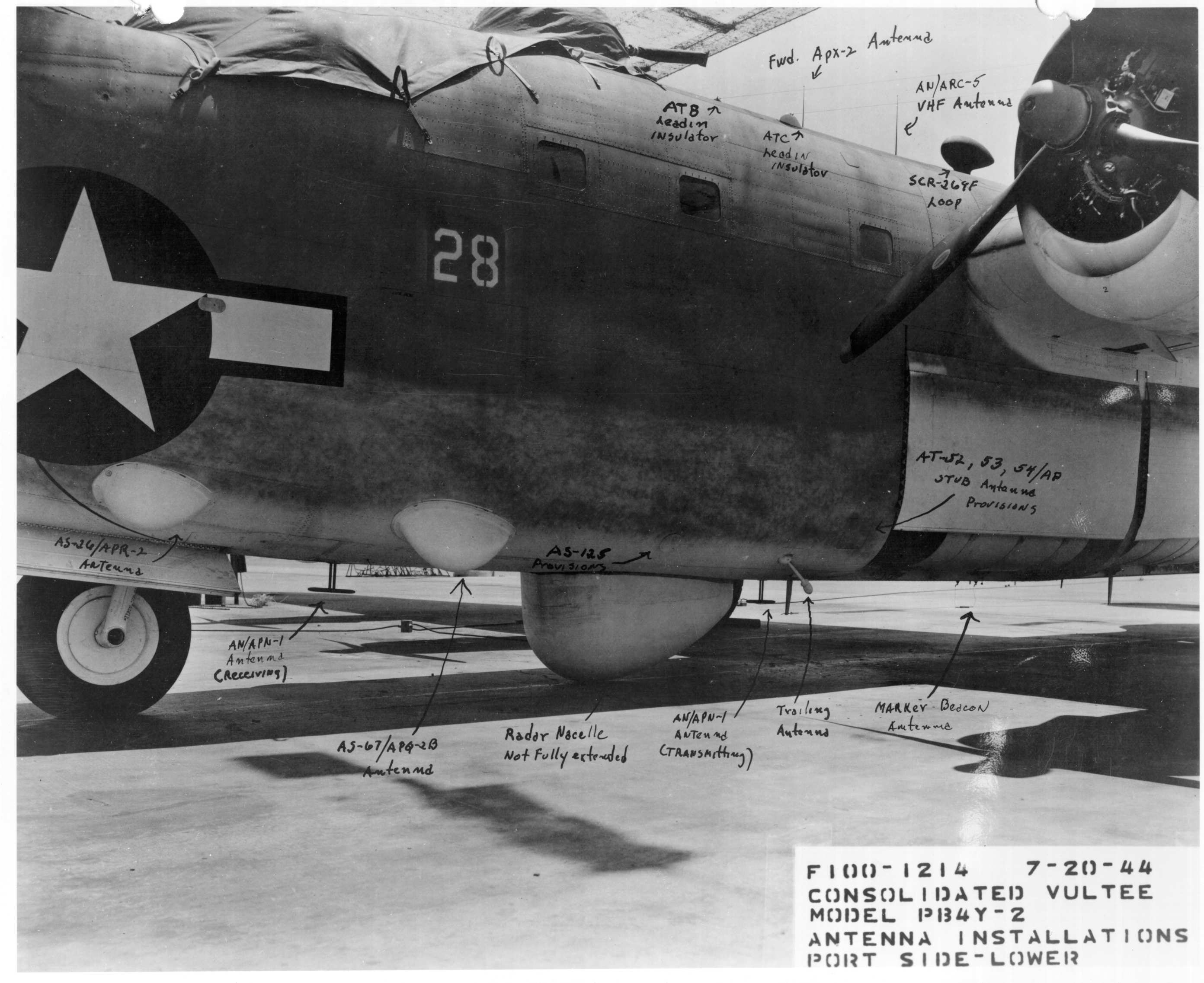 Antenna installations, port side lower
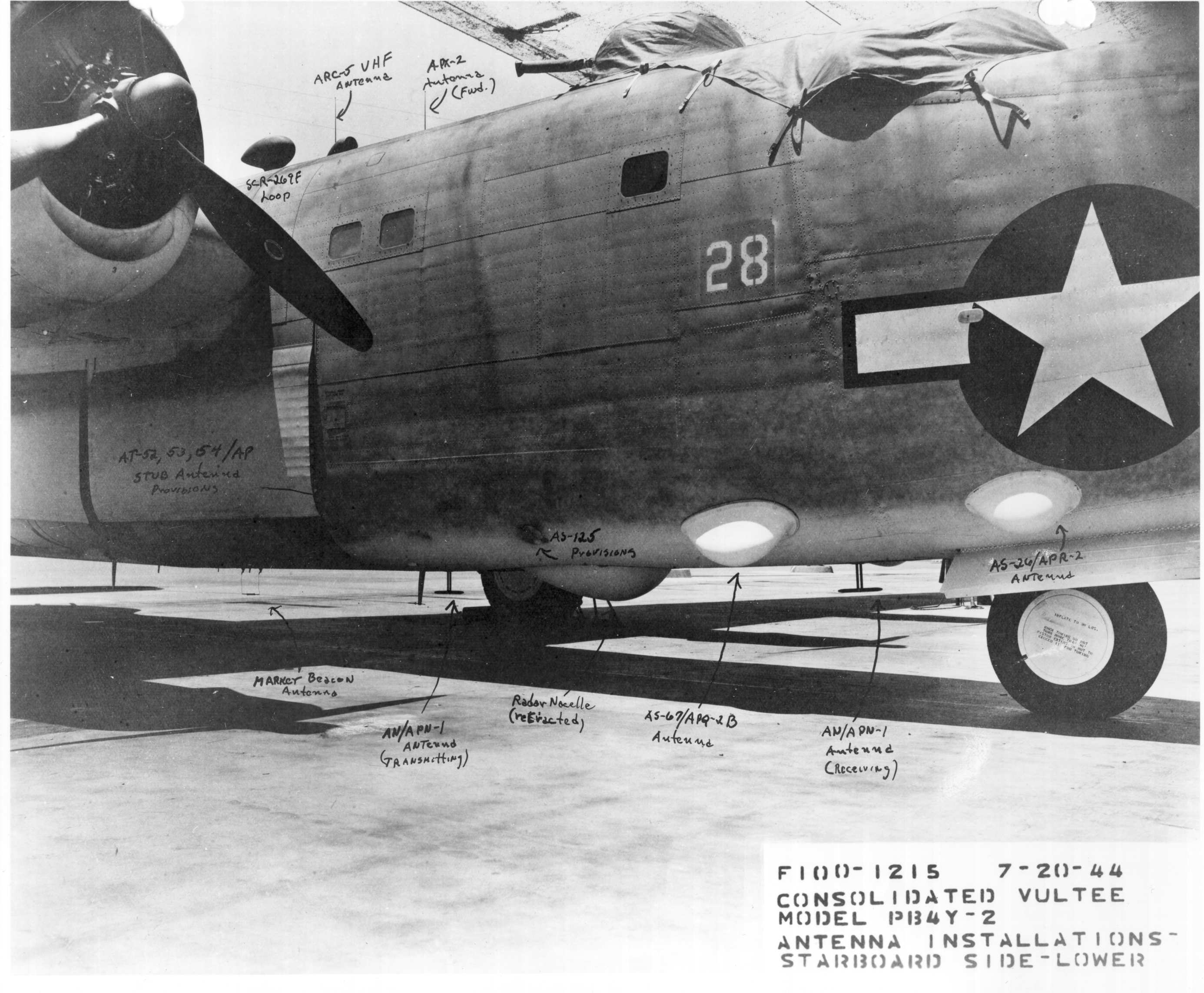 Antenna installations, starboard side lower
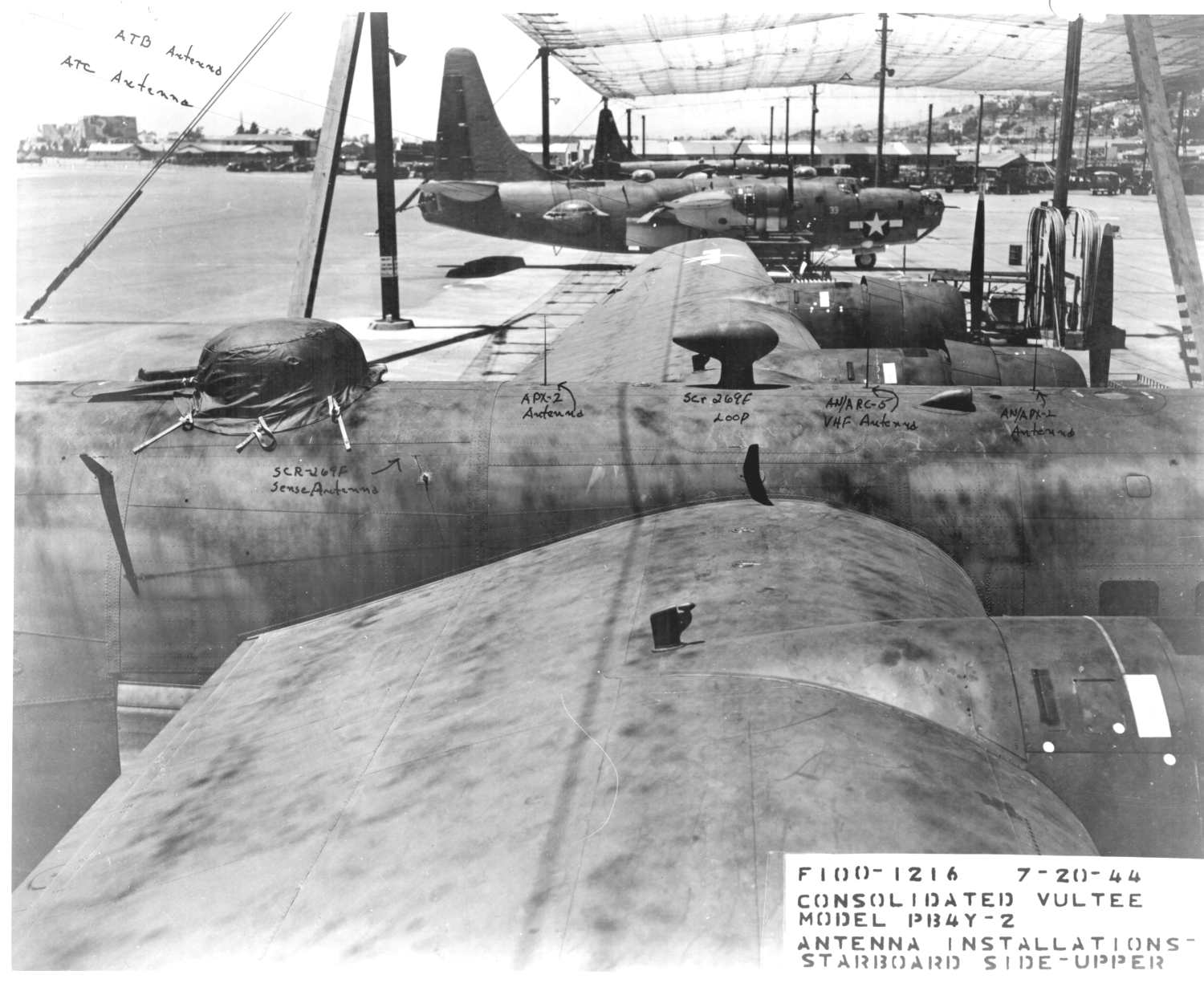 Antenna installations, starboard side upper
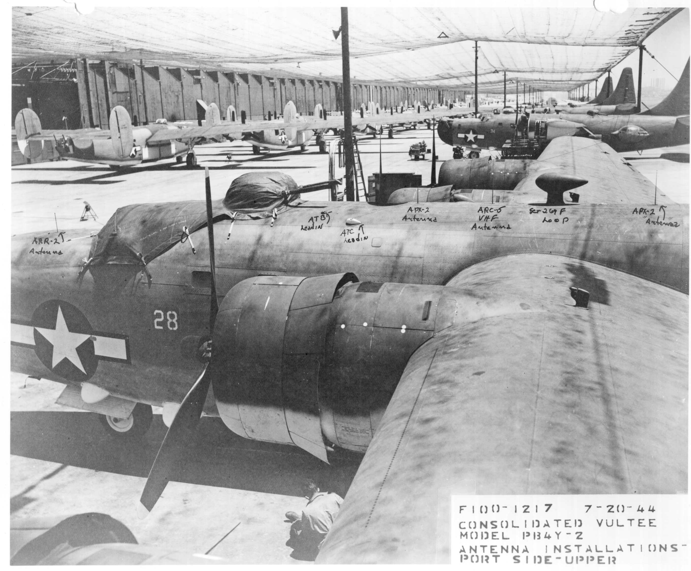 Antenna installations, port side upper
Return to AAFRadio