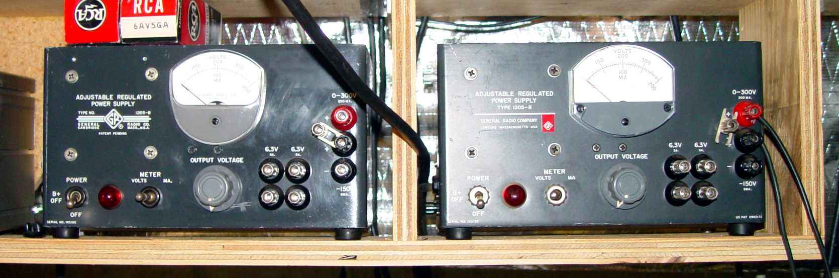
Early and late 1205-B power supplies
I acquired a couple of these neat little supplies during the heady days of hamfesting in the 1990s, each for $15 apiece. They have been invaluable in restoring old military aircraft sets from WWII, as well as other vintage equipment that had not been used for years. Fast forward to this year, and I found that after a long period of disuse both had stopped working properly, so I decided to refresh the supplies and bring them up to date with a few more modern components.
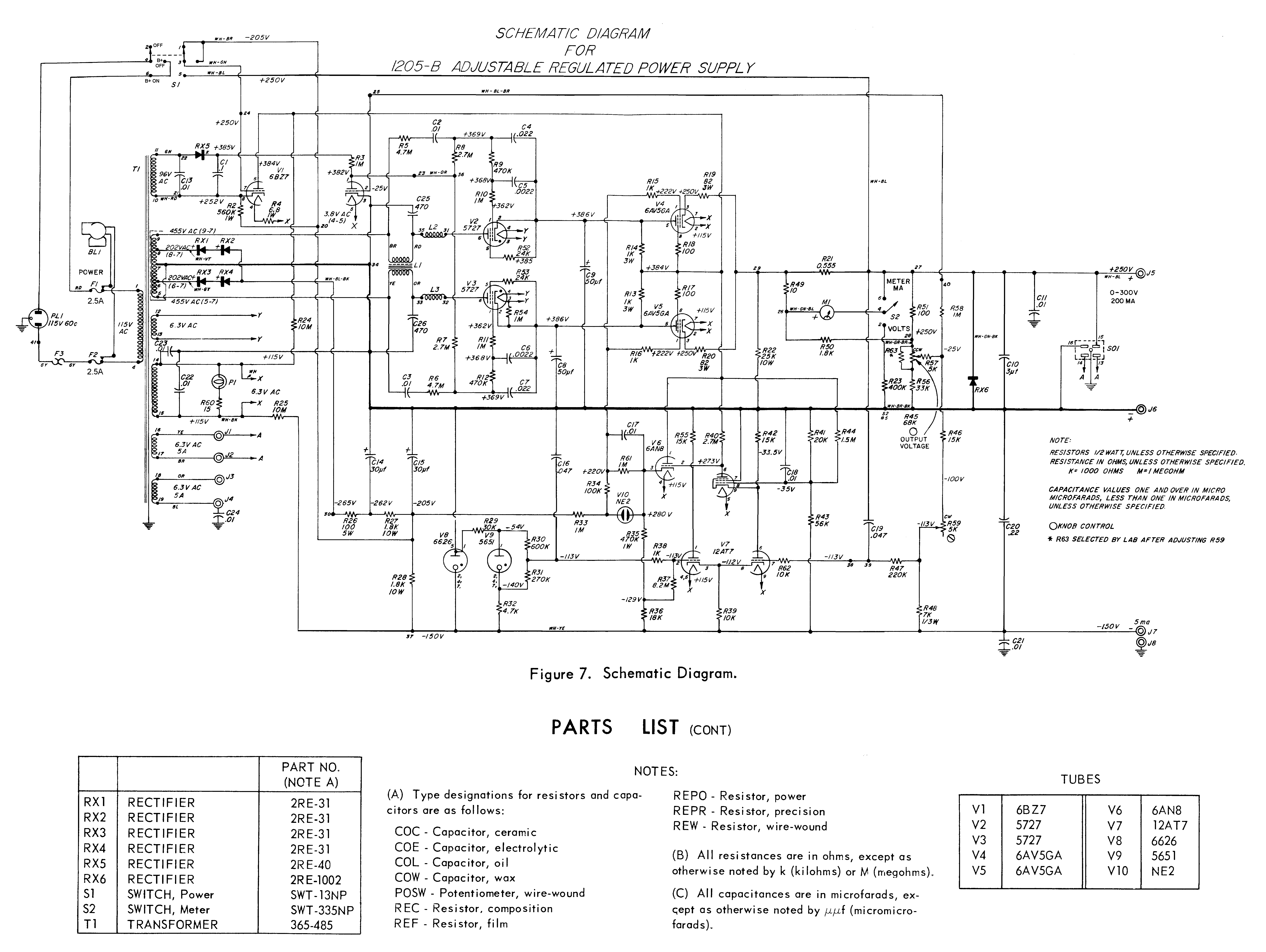
There are actually several small changes between the early and late model supplies, not the least of which is the shape of the meter. A comparison between the original 1959 manual and the 1965 manual will reveal these minor changes, most particularly in the schematics. Since the 1959 Revision A manual seems universally available on the internet, I have scanned and posted the April 1965 Revision C manual here. Strangely, there is no indication in either manual as to what serial numbers either one covers. That might have been useful to know.
In recent short testing periods I had found both of these supplies to have the dreaded low output voltage syndrome. They would start out in the vicinity of 200 volts DC with full clockwise rotation of the output voltage control, and gradually edge downward as the supplies warmed up. Not wishing to blow any electrolytics (one supply already had the indications of that happening sometime in its past life), I kept these sessions short. Measuring electrolytic temperatures with a laser thermometer after five minutes, it was obvious that all were leaky, so I bit the bullet and ordered some new ones from AES.
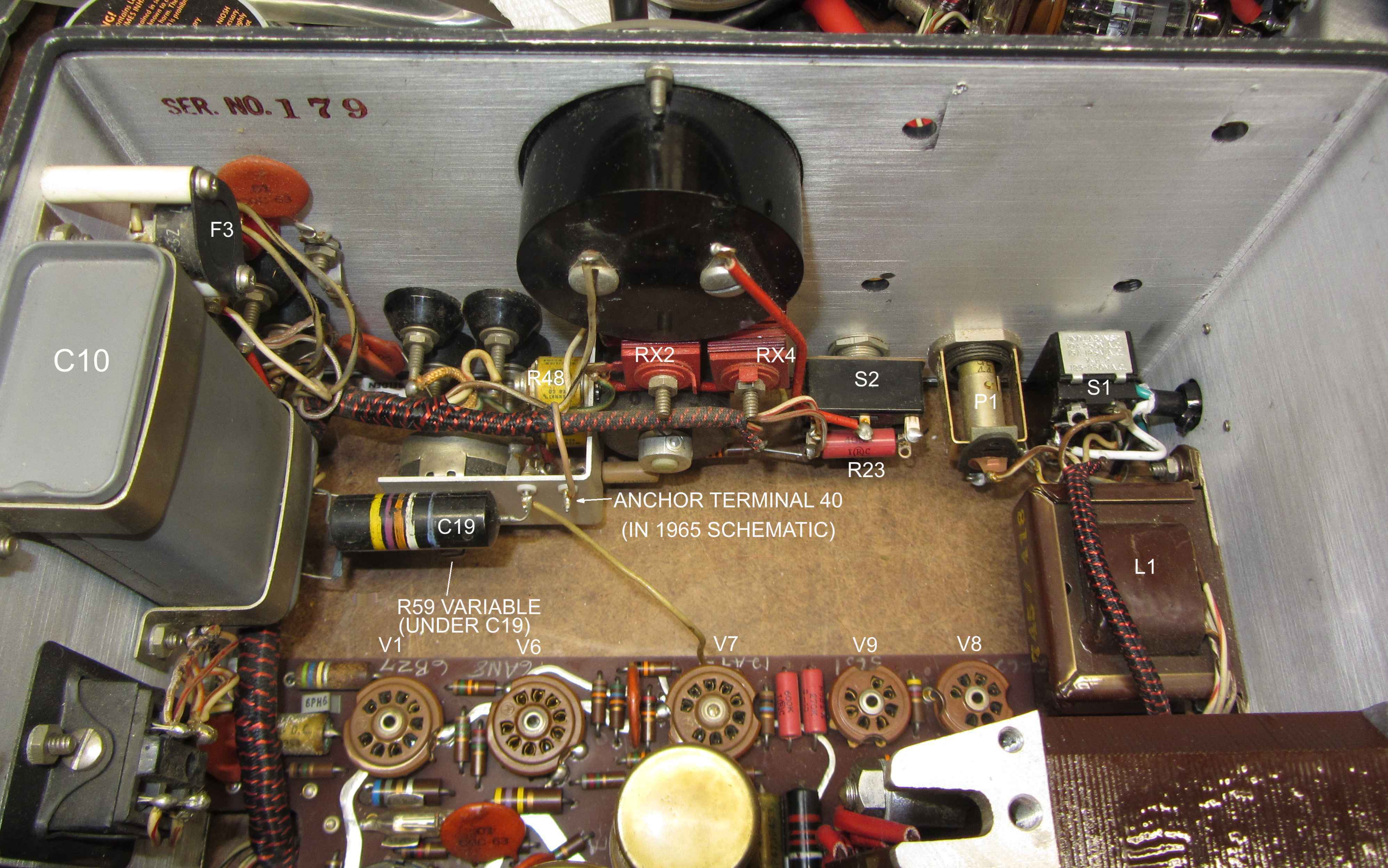
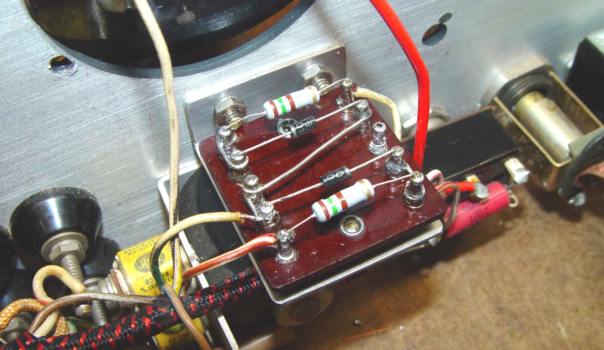
Below is the starting point "before" photo for both the capacitor replacement and selenium rectifier replacement. One thing I noticed between the two manuals was that the location of Anchor Terminal 40 was not the same. The 1959 schematic shows it at the voltage control pot side of R58 (1 MegOhm 1/2w), while the the 1965 schematic shows it at the 6BZ7 side. You can see in the photo below the location that is reflected in the 1965 schematic. In normal operation, there is an negligible amount of current through R58, so the difference in the -25 volts DC on either side of the resistor cannot be seen with an analog voltmeter. The later post location is also much easier to connect to a test clip. Two other changes to the 1965 manual are the insertion of a 10k 1/2w resistor to grid pin 7 of the 12AT7, and the connection of a new R63 across the voltage control pot. The manual cryptically states: "R63 selected by lab after adjusting R59" (the zero-set adjustment). No further clue is available in the manual as to what this resistor might have been meant to accomplish, or how one is to optimize its value. There was no sign that it had ever been installed in my later supply.
Over the years I have gradually collected a box full of terminal boards for various uses. My first inclination was to use a couple of small ceramic strips from a parted-out Tektronix oscilloscope, but the 1205-Bs are extremely compact, and stuffing the high profile Tek strips somewhere in the vicinity of the original selenium rectifiers just didn't seem practical. I also didn't want to drill any new holes in the supplies, preferring to use the mounting holes that were left after removing the seleniums. The board pictured below fit perfectly, but needed to be mounted at right angles to the front panel to fit, so I fabricated a .062" thick stainless bracket to hold the board in the correct position. That seemed to work fine, although there was no way to avoid pulling out the meter to have any room to install the bracket. Some patience is required to get the front panel nuts threaded and tightened down. They say it builds character,...
One thing that irritated me about working on these supplies is the PVC insulation on the wires. The touch of a soldering iron to the conductors has to be incredibly brief to avoid melting the insulation. I was using my usual Tektronix 3% silver bearing solder to reduce the damage to terminals and the like, but that doesn't help the fade-back of the insulation every time you warm it appreciably. It helps to be aware of it so you can reduce the exposure time.
The capacitor replacement part of the project was a bit more involved. I initially thought about using the Pace vacuum desoldering station to remove as much solder as possible from the bottom printed circuit lands of the three big cans on each supply. Surely they would then simply fall right out. He said confidently...
The reality is more complex. First, the printed circuit board used in these supplies is a relatively low grade material, not the usually green fiberglass with gold plated lands used in higher priced equipment. Secondly, there are a total of either five or seven prongs from each capacitor that is soldered after inserting the can into the board. One of the supplies already had a land broken in removing one of the cans in a past life, and I wasn't in the mood to raise the damage level any further. Yes, I know there will be those who say it's easy and question my sanity, but as a preservationist, my first rule is, "do no harm." So I took another approach and used a Dremel tool to cut the cans off near the base. I was aided in this decision by a corollary to the old adage, "To a man with a hammer, everything looks like a nail". In this case, the corollary asserts, "To a guy with a lathe, everything looks like a fun project, even if it's way more complicated".
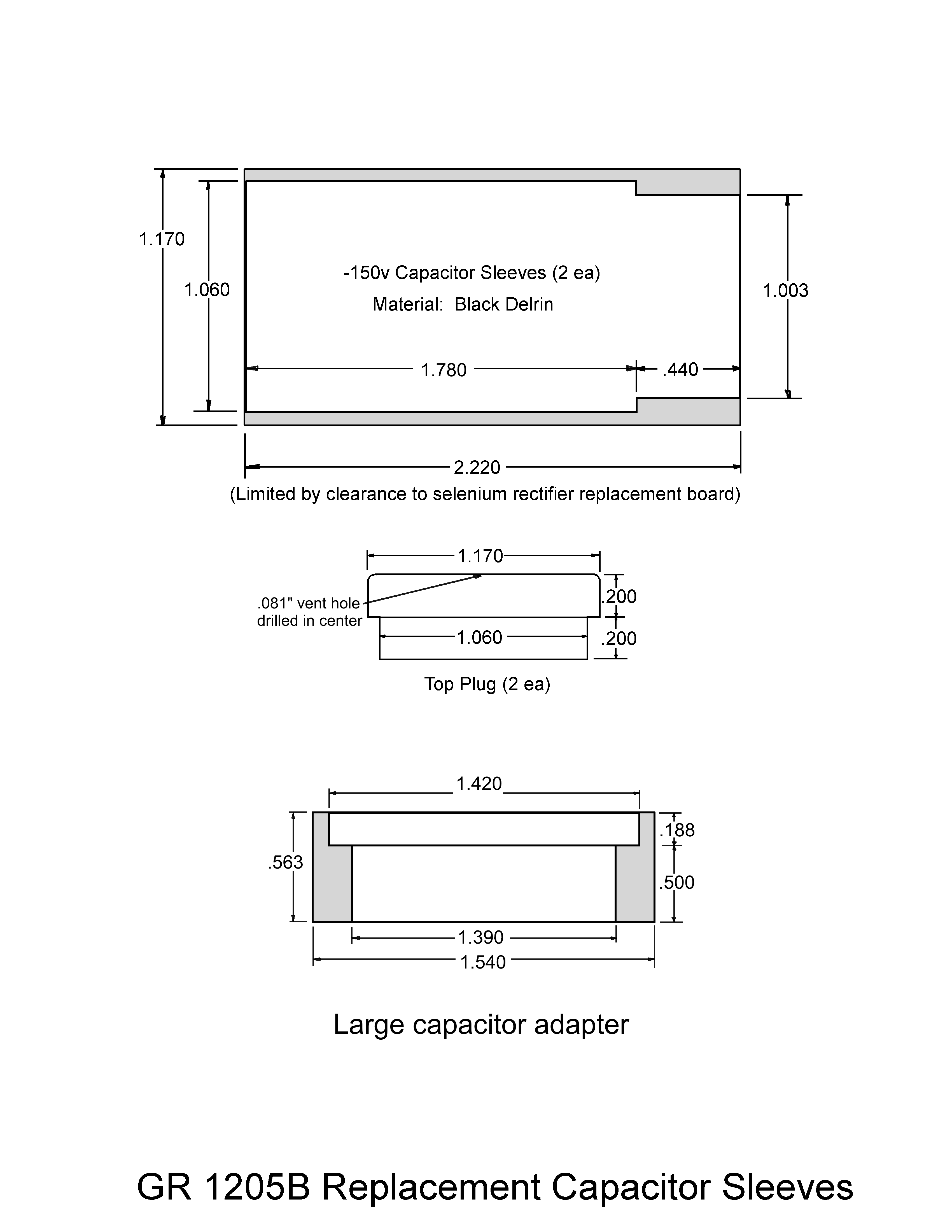
I had acquired some bars of black acetal copolymer (black Delrin) for another project and decided to use some of it for this task. The new 50/50uF B+ capacitor simply needed an adapter to connect the original can remnants to its bottom, but the other two caps had axial leads, so I made tubes that entirely enclosed them. A fabrication sketch follows the photo below of the finished product. The capacitors are stabilized by pulling them into the adapter and sleeves through .060" holes drilled in the phenolic bottom of the original can, then soldered to the appropriate terminals underneath. The Delrin parts are epoxied to the stub of each orignal can. Note well the mention of selenium rectifier board clearance in the fabrication sketch. The photo below shows what happens when you don't install the top plug on the far right hand sleeve before rotating the circuit board back to its stowed position. There is not quite enough room to slide the plug on in that buttoned-up condition...duh. (I've since opened up the supply and corrected that oversight.)
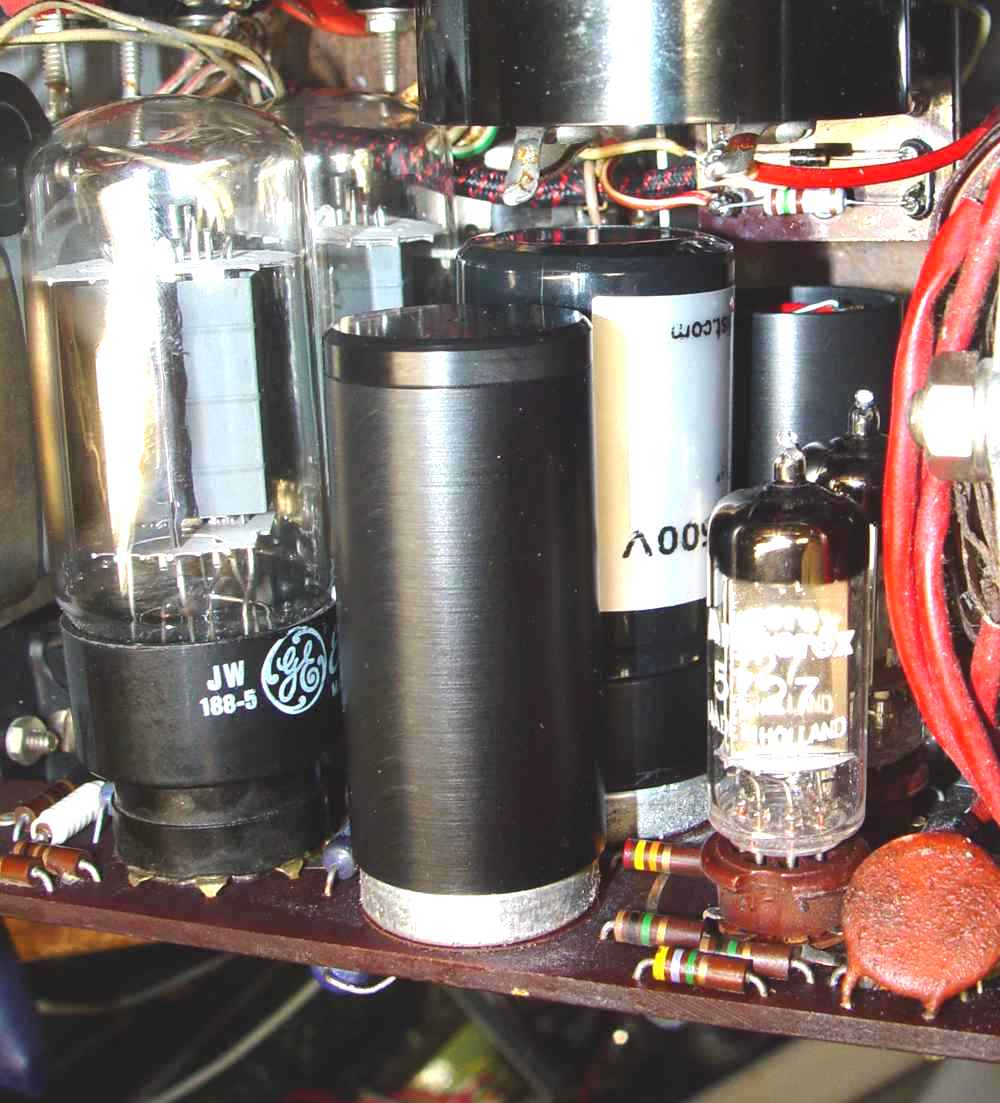
Now...I wish I could report that both supplies stood up and flew right once I had done all this work, but it wasn't meant to be. The output voltage at full clockwise control position was only a little higher than 200 volts DC. A bit of tracing, and the voltages were puzzling. Pulling the 6AV5 series regulator tubes to break the feedback loop and feeding the output terminals with +250 volts showed a very close match to the voltages in the 12AT7 regulator section. Just to make sure, I replaced the two 10 Megohm resistors R24 and R25 with 1% metal film resistors because they had drifted outside of their 5% marking. Then I noticed that there was one of the infamous "Black Beauty" capacitors marked C19 (see second photo near the top of this page - original interior corresponding to Figure 4 in the 1959 manual). Its sole purpose is to feed back ripple voltage to the differential amplifier stage provided by the 12AT7 (V7), and I had checked it earlier with a good digital LCR meter. The readings didn't seem too bad, with over a megohm leakage resistance for the cap in each supply. Acting on a hunch, I clipped the lead on one side of the cap, and WooHoo! Everything worked perfectly. A new .047uF 600v film capacitor, as well as similar caps to replace the two smaller Black Beauties in each supply, and the ripple reduced from 100mV to less than a millivolt. The voltage now tops out at 320 volts DC in both supplies. I finally came to the conclusion that even a high capacitor Rp (>1 megohm in both Black Beauties) produced enough leakage current (~300uA over a 363 volt drop through C19) to imbalance the regulator without showing more than a volt in difference from the schematic test value (-113 volts DC at grid pin 7 of the 12AT7). Just for future reference, here are the 120Hz measurements from both the BBs (averaged) and the film replacement for C19:
BB Cp= 0.050 uF (schematic value .047uF)
BB Rp=1.03 Megohm
BB Q=39.1
BB DF=0.025
BB Ѳ= 88.5°
Film Cp=0.048 uF (schematic value .047uF)
Film Rp=off scale
Film Q=off scale
Film DF=0.000
Film Ѳ= 90.0°
And for completeness, here are the measurements for the two smaller Black Beauties in the phasing network of the thyratrons:
BB #2 Cp= 0.0036 uF (schematic value .0022uF)
BB #2 Rp=2.39 Megohm
BB #2 Q=6.37
BB #2 DF=0.159
BB #2 Ѳ= 81.1°
BB #3 Cp=0.0029 uF (schematic value .0022uF)
BB #3 Rp=4.95 Megohm
BB #3 Q=10.76
BB #3 DF=0.092
BB #3 Ѳ= 84.6°
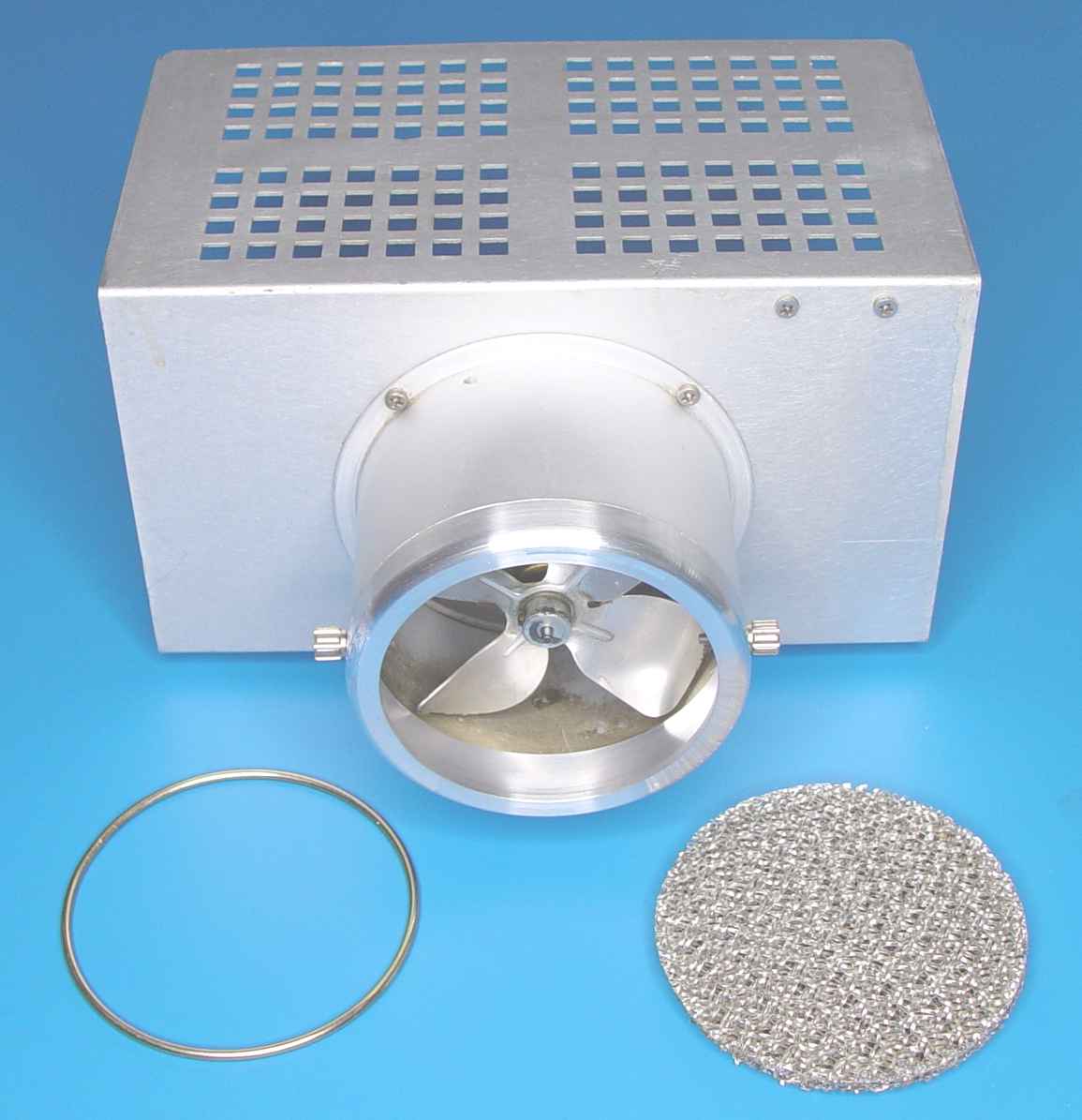
The only thing left to do was to fabricate a missing air filter bezel for the fan in the rear of one of the supplies, using the dimensions from the other supply bezel. (Refer back to the "Man with a Hammer" adage/corollary.)
Happy hammering...