Every now and then I get drawn into something that piques my interest, even when I have a premonition that it may get convoluted beyond any reasonable bounds. When I acquired the original shock mounts for my GO-9 transmitter, I remember vaguely hoping that I would never have to make replicas of them because of two simple characteristics - 1) dozens of piece parts, almost all made from stainless steel and in oddball sizes and shapes, and 2) some heavy duty bends required in 3/32" stainless plate that would tax a sheet metal brake far larger than what I had available in my shop. Best laid plans much later, K4CHE (Zorro) caught the GO-9 fever and found one sans shocks of any sort. That seemed like a good time to consider what might be done to duplicate the ambiance of the mounts, if not the precise materials and fabrication details.
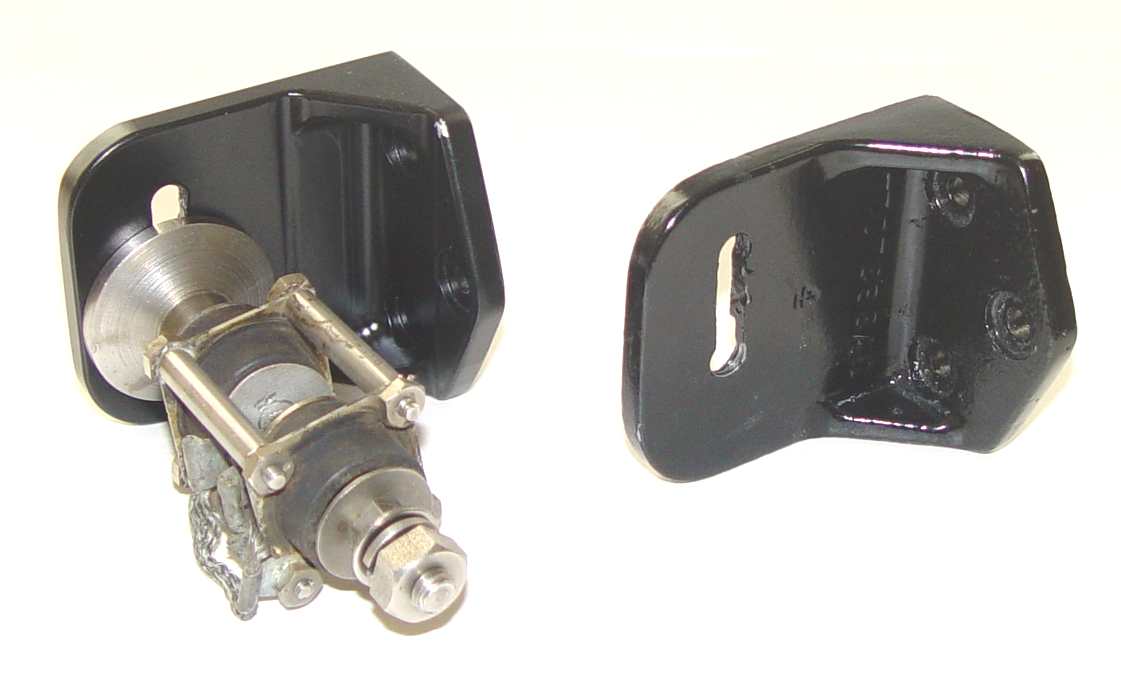
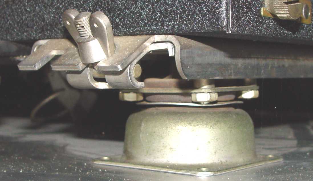
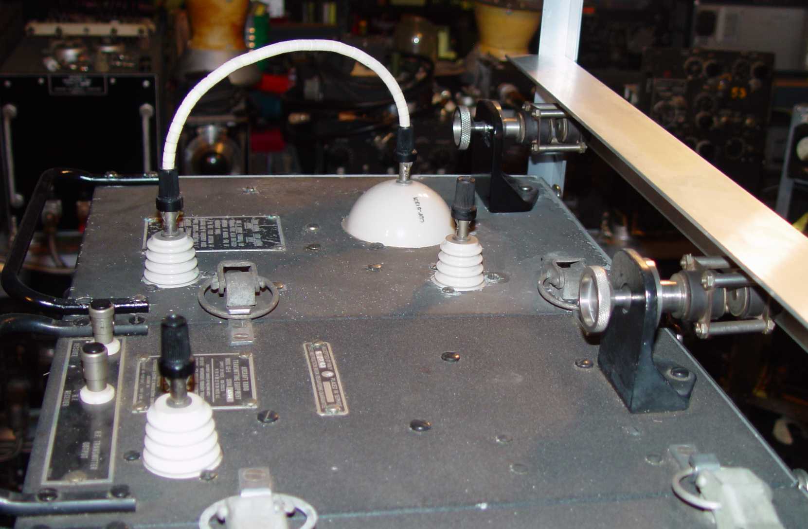
We started off with an advantage - a complete spare lower shock mount for the transmitter that I inherited from N3NNG (slightly corroded but would clean up nicely), and of course the rest of the mounts in my own set to serve as models. I started with the bottom mount (an original is shown here with the transmitter in place on top:)
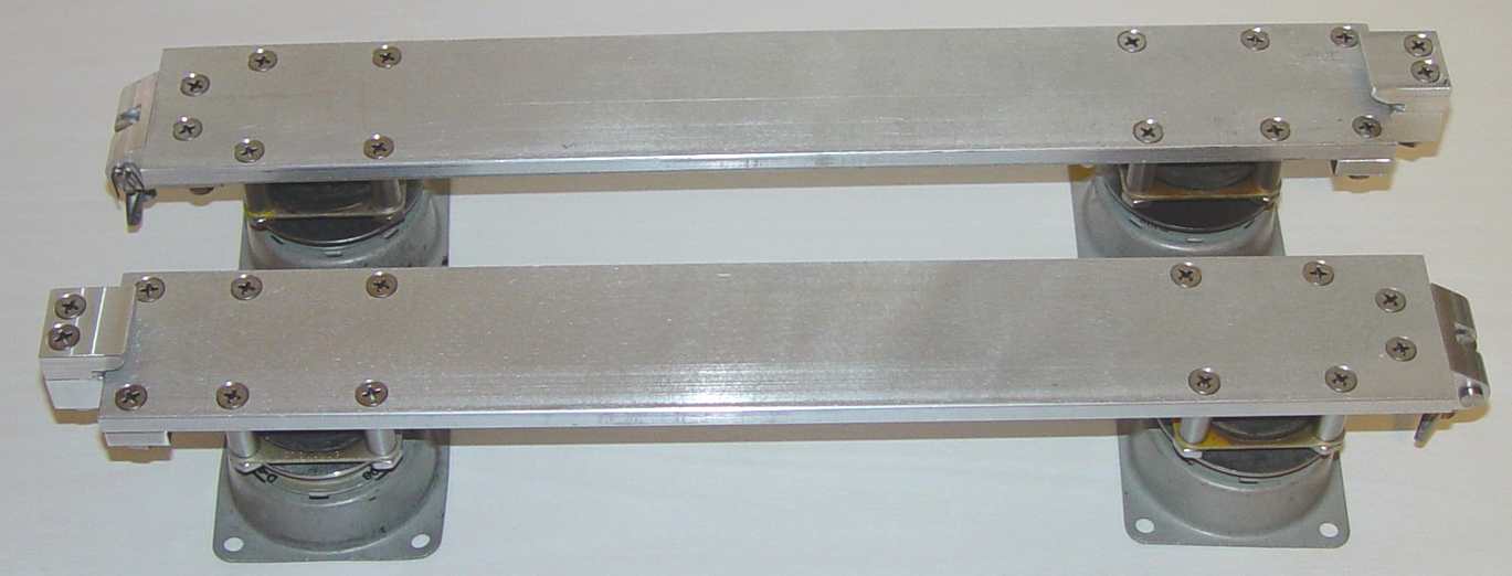
Z had a piece of 2.5" x .25" aluminum bar stock, which was a good start for the lower rails of the end transmitters, so we were off and running. "How hard could it be?" muttered Hanz Quixoté, nervously stroking his chin with fingers already slippery with cutting fluid... Z did his best to fill the essential role of Sancho Panza and provide some necessary grounding in reality (a state of mind that I continually resisted despite his best efforts,) but I was being driven by the engineers' creed: "Why make something simple, when with some imagination you can make it unnecessarily complicated?"
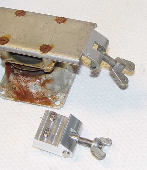
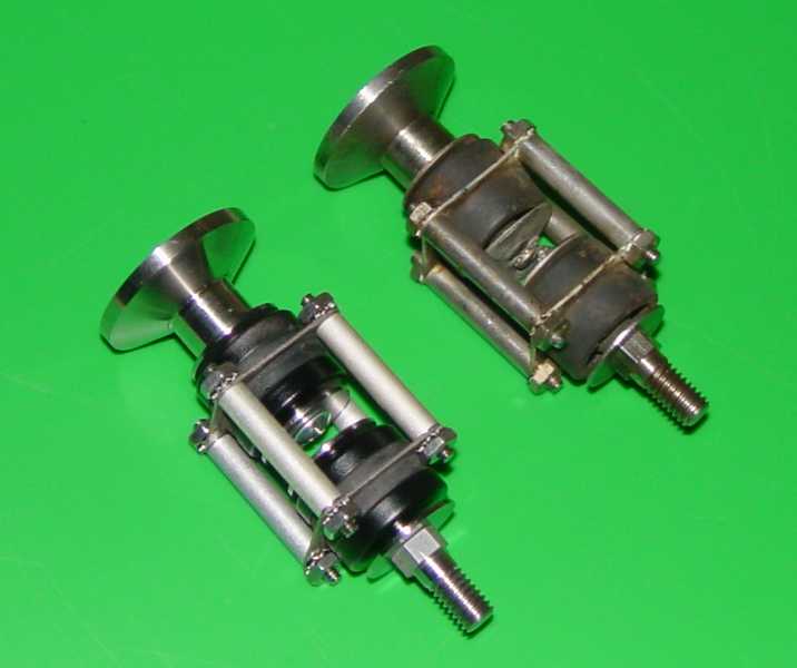
The first task was to consider how to transform the end of the aluminum bar into something resembling the original stainless mount. Fortunately, any resulting assemblage is beneath the mating transmitter rail, and all one normally sees is the wingnut when the transmitter is mounted on top, so some latitude is possible.
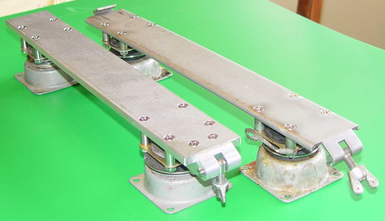
Some adjustments needed to be made to the height of spacers, etc. because is wasn't possible to find the original 20 pound Lord shock units. Only lower capacity shocks were available, so some creative bumper disks had to be made to prevent collapse under the weight of the transmitter units. The photo below shows an almost finished product, minus the rear capture piece to accept a lip on the rear of each transmitter.
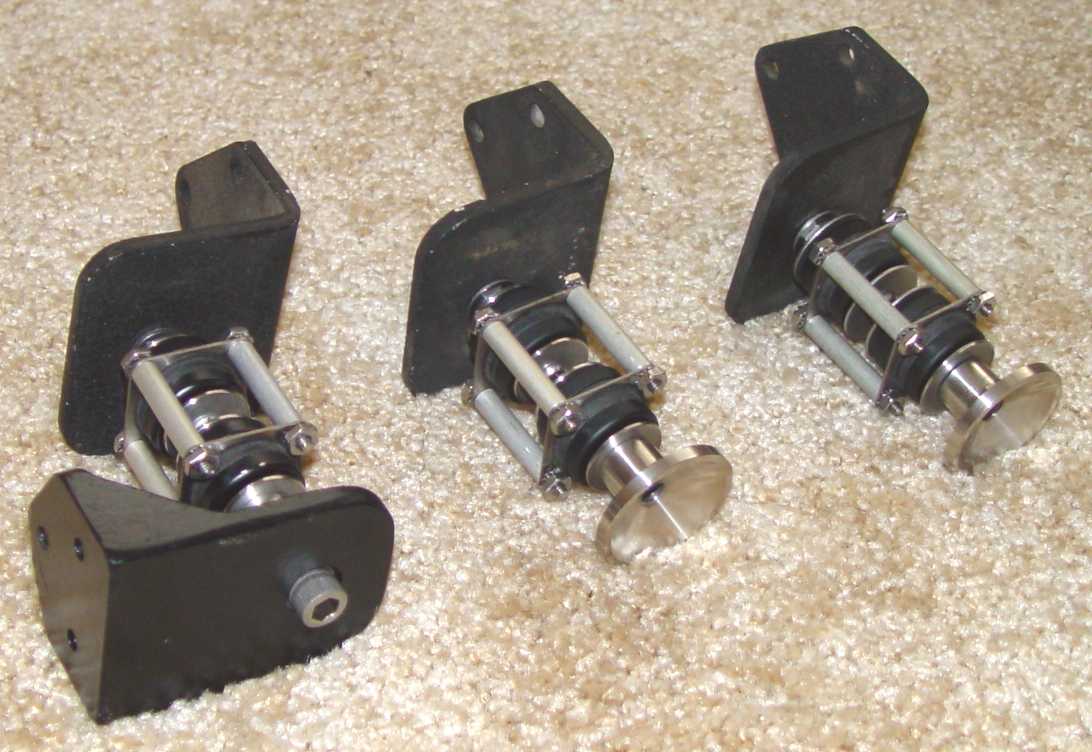
The top anti-sway shocks were real time consumers, even after I finally figured out how to produce a shock unit that looked like the thick originals. There are 36 individual pieces in this contraption! The only stock parts I could find to use were the much lighter capacity Lord shock units along with 6-32 lockwashers and nuts. Everything else required some level of machining, either from stainless bar or cutting down and modification of standard parts like washers.
One last detail - the HF transmitter was missing its top anti-sway bracket. The originals were cast aluminum, but lacking a casting facility, I simply carved it out of a solid block of aluminum. That produces lots of chips...