This particular table was an eBay-acquired 15" model, in fairly nice condition but needing a good cleaning and new
paint job to match the looks of the restored mill. Standing it up on its back edge revealed a large nut
with two holes meant for a pin wrench, along with a gush of fetid lubricating fluid from the bowels of the
table. Okay, the instructions on the front said not to *invert* it, nothing about turning it on its back
edge... :-) The solution to removing the nut looked simple...just make a wrench out of a spare 1/2" thick
piece of 3" diameter CRS on hand. What could be easier? Decided to make a pin wrench that would both remove this
nut and the lower quill nut on the Bridgeport - that needed a good cleaning and the collet locating pin in
the spindle needed replacing anyway. Measured the pin distance. Hmmm, not the same, not even the same pin diameter!
Oh well, close enough to allow one pair of pins on one side and another on the opposite face. Spent an hour
happily making chips on the lathe and mill, finally plugged in the pins with some Loctite. Before removing
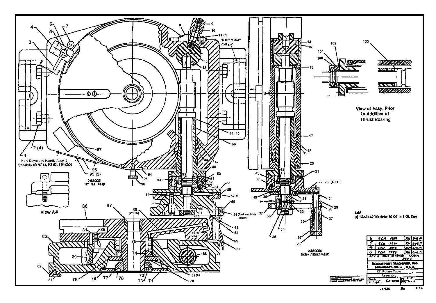
the nut on the bottom of the rotary table, it's necessary to remove the closure plate on the bottom, retained by
4 flat head screws. Some care is necessary, as there is a large O-ring on the inner diameter of the closure plate
that is easily nicked. Removal allows access to the side of the nut, where one finds an Allen head set screw
bearing on a brass locking pin. Backing off on the set screw first prevents all sorts of dire consequences to
the threads...I highly recommend it. ![]() The nut retains a large thrust bearing that prevents the table from
lifting upward under heavy milling. Removed the nut with a smug expression of satisfaction at the way the wrench
worked. Peered inside the hole, and to my consternation see yet another nut buried 2" deep in a cylindrical
cavity just slightly larger than the nut. At least the pins are the same dimensions and distance apart. Staring
in dismay at the 1/2" thick pin wrench hot off the mill, I finally decide you can't get there from here and begin
looking for the material needed to make a longer wrench.
The nut retains a large thrust bearing that prevents the table from
lifting upward under heavy milling. Removed the nut with a smug expression of satisfaction at the way the wrench
worked. Peered inside the hole, and to my consternation see yet another nut buried 2" deep in a cylindrical
cavity just slightly larger than the nut. At least the pins are the same dimensions and distance apart. Staring
in dismay at the 1/2" thick pin wrench hot off the mill, I finally decide you can't get there from here and begin
looking for the material needed to make a longer wrench.
Two hours later, dirty and disheveled, I emerge from the basement darkness with the only stock that will remotely do the job - a 10" long piece of 6" diameter aluminum. No problem, I say to myself, it still fits in the 10" South Bend. Now, I'm here to tell you that it's amazing how much aluminum swarf you get when you turn a bar down from 6" to 3" in diameter. Momentarily considered renting a Bobcat with a bucket to clean out the garage, but cooler heads (my wife's) prevailed, and I spent the next hour sweeping up a barrel of chips. Drill and set the pins, then carefully remove the nut with the new tool, not quite so smugly this time. I had this horrible moment of panic as I unscrewed this second nut, suddenly visualizing yet a third nut underneath the second, maybe even a fourth under the third, and realizing that I sized the length of the tool just long enough to reach to the surface of the second nut and no more, but Murphy was kind to me. A few taps with a big brass drift and the table slid out of the base.
One thing I hate about water based flood coolant systems is that they seem to get into everything, and the reservoir beneath the rotating table is no exception, despite the lack of an obvious entry route. I scooped out all sorts of really appetizing 'stuff' and rust, all possessing the tantalizing aroma of a long-dead swamp rat. Two weeks later, holding my breath all the while (okay, maybe I didn't work on it every minute), I finally had the base cleaned out and primed with new Rustoleum. I still get a whiff of the smell every time I walk by the trash can, though.
I didn't bother to remove the worm shaft assembly, partially because it looked like it was in fine shape and partially because masking it off was a lot easier than pulling it out. Painting the base was easy, once all the chips and pits had been filled and sanded. Didn't try to make it into an show car finish, but it came out looking like new.
The circular table disk came next. There are two oil channels drilled into the periphery, one of which feeds a radial groove ground into the bottom surface of the table. This bottom surface is finely machined and scraped, forming a large thrust bearing. On mine, the Gits oiler was missing the ball so I had to take it out with a drill, and blew out a huge amount of debris in the process of cleaning it. The other oiler feeds a long passage stuffed with a rope wick, gradually dripping oil on the top of the central roller bearing. It was clear, so I didn't bother to clean it. A Scotchbrite pad cleaned off the rust and other coatings off the bare cast iron surfaces that wouldn't get painted. WD-40 or CRC will keep those relatively bright, though I do wish I could find a cast iron polish that would work halfway well without darkening the surface.
Reassembly was relatively uneventful (unusual for me), but there were some interesting data points. The huge central bearing has a separate inner race that is an incredibly tight fit into the rollers. Since it fulfills an important role in achieving the accuracy specification, that makes sense, but it is definitely not a "lubricate and slide in by hand"operation. I took the table apart with it standing on-end (a couple of plywood boards prevented "oops" accidents if it had turned over.) Putting it back together, it seemed better to place the base horizontally and set the rotating table into the bearing, then tap it in with a brass drift. A slathering of synthetic way lube on everything seemed to help, and the table finally seated against the base. I had set the table up on a couple of 6"x6"x6" wooden blocks so I could reach underneath and avoid having to flip 220 pounds of cast iron around. There was enough room to put the bearing retaining nut on and cinch it up, then slip the bottom thrust bearing on. I used some EP grease on this bottom thrust face because there's no obvious route to receive much way lube from above. Seemed to work fine. With the worm shaft disengaged, I kept spinning the table and tightening the nut until I felt a slight drag, then locked the nut with the set screw.
Back up at the worm shaft, I had broken it down to as far as the first thrust bearing in order to polish up the handwheel and fiduciaries, as well as clean everything. There is a cylindrical nut on this shaft that adjusts end play, buried under the cup that has the small oiler on top. Someone had let this adjustment get awry, and the two aluminum fiduciaries had started to grind away at each other in the clockwise direction. Not serious, but it made an awful noise in the midst of otherwise beautifully smooth, oily motion. It takes some effort to get this nut backed off to where it will turn, as it is retained by the usual set screw and brass locking pin, but it was possible to reduce the thrust bearing end play to essentially zero by tightening this up just finger tight. The only other adjustment of consequence is the degree of engagement of the worm gear with the ring gear on the table. That's done by loosening two button head cap screws on either side of the "on-off" lever escutcheon on the right rear and gently adjusting the gear mesh for full engagement.
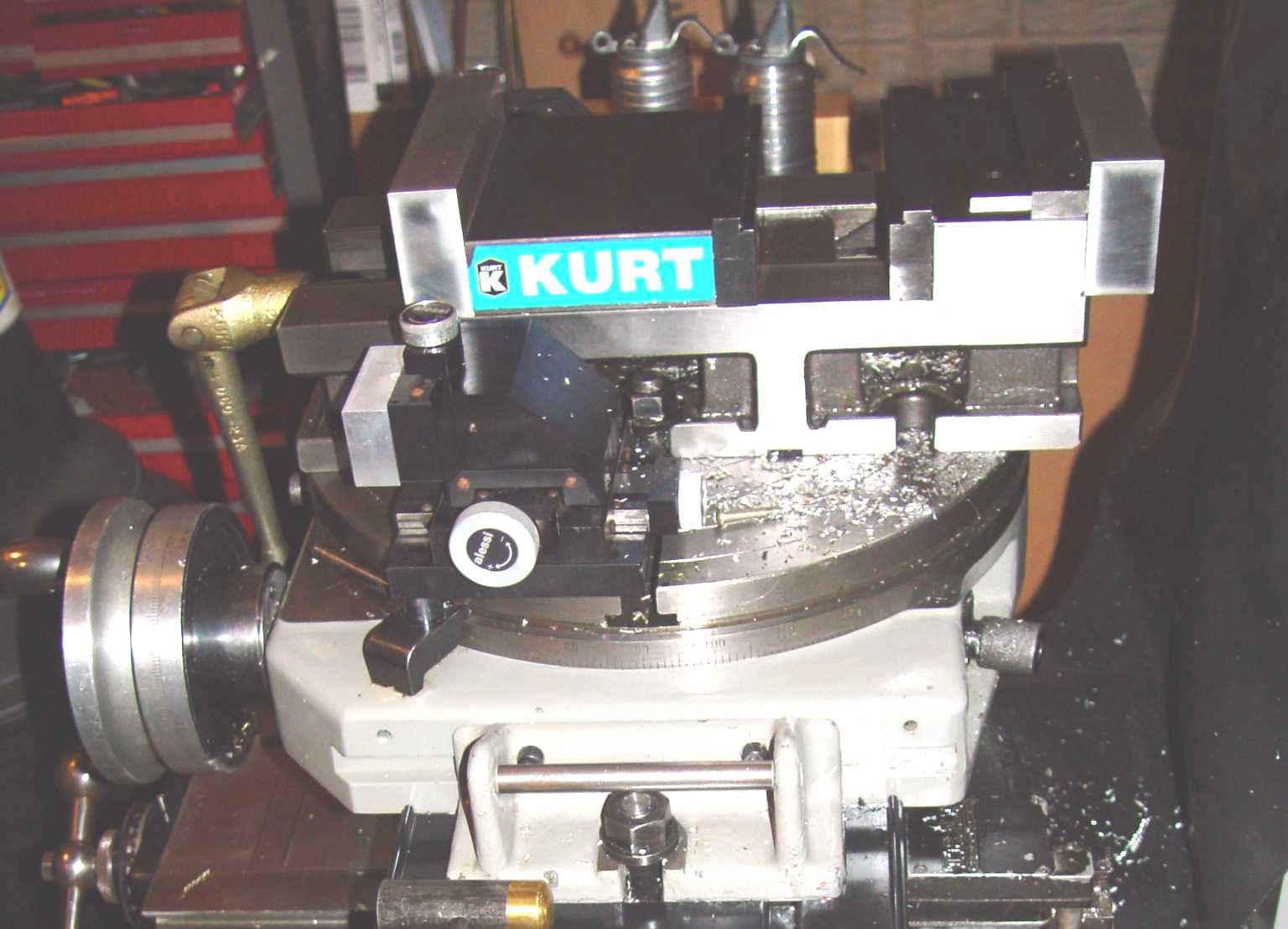
Getting well over 200 pounds of rotary table up on the Bridgeport table was a two-man job, but it has turned out to be more or less a permanent fixture there for the majority of my type of work. It's now a lot easier to return the vise to exactly zero or 90 degrees than with the swivel base that came with the milling vise. The surface is large enough to clamp most of my projects, so I won't have to pull it off very often. It also offered the opportunity to stick in a 7" riser I bought some time ago but hadn't installed because most milling would then need to be done with the quill extended too far. In addition, the added mass has made a difference in surface finish for heavy cutting, and the whole mill has settled down a bit more during most milling operations despite the Bridgeport's pechant for flexibility compared to the larger mills. Besides, the table looks cool just sitting on the Bridgeport! :-)
Mike Hanz