I get an occasional question about how I go about making a mount for a given WWII radio or peripheral, and I thought an example might be the most useful way of demonstrating that process. Usually these mounts are as scarce as hen's teeth, even for avionics that were produced in large quantities, so a certain amount of guesswork is involved, along with clues from photographs and manuals. Luckily, the general construction is fairly common, so a mount for a similar piece of equipment can form the basis for duplicating the missing mount. Manuals can be of immense help for overall dimensions, but photos often show the mount buried under the equipment, so a certain amount of creative license occasionally has to be applied. That was the case with this particular mount, for an oscillator used with the early SCR-183 equipment.
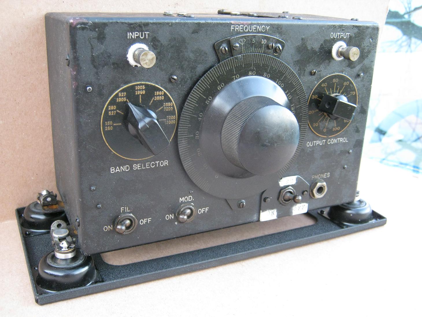
In the early 1930s, aircraft radio receiver design technology centered around the conventional Tuned Radio Frequency (TRF) configuration, the superior superheterodyne approach (using a mixer stage) still being somewhere off in the future. Even CW reception was a problem because of the lack of a BFO. Also, since receiver tuning dials of the era were normally of small diameter and simply calibrated from 0 to 100, a need surfaced for a stable and accurate oscillator that could be used both to function as a BFO, and to be able to set reception and transmission frequencies accurately while in flight. The BC-RC-183 oscillator was designed to fill that need for the SCR-183 set. There were no direct reading frequency dials with this oscillator either, but with the larger dial you could read the number with precision (aided by the vernier fiduciary), and through a look-up table determine frequencies quite accurately.
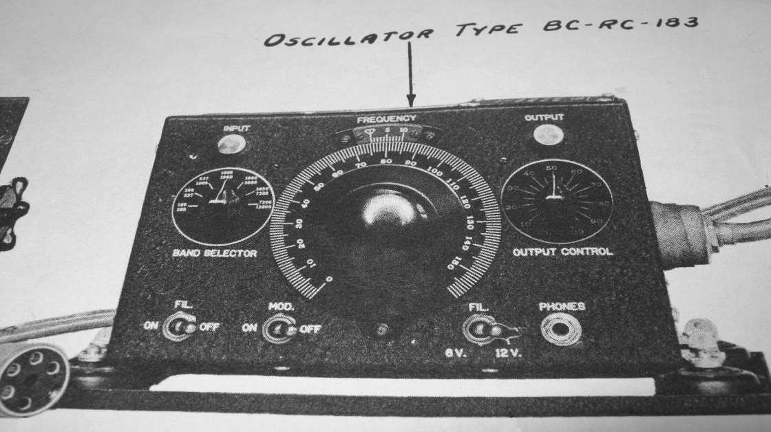
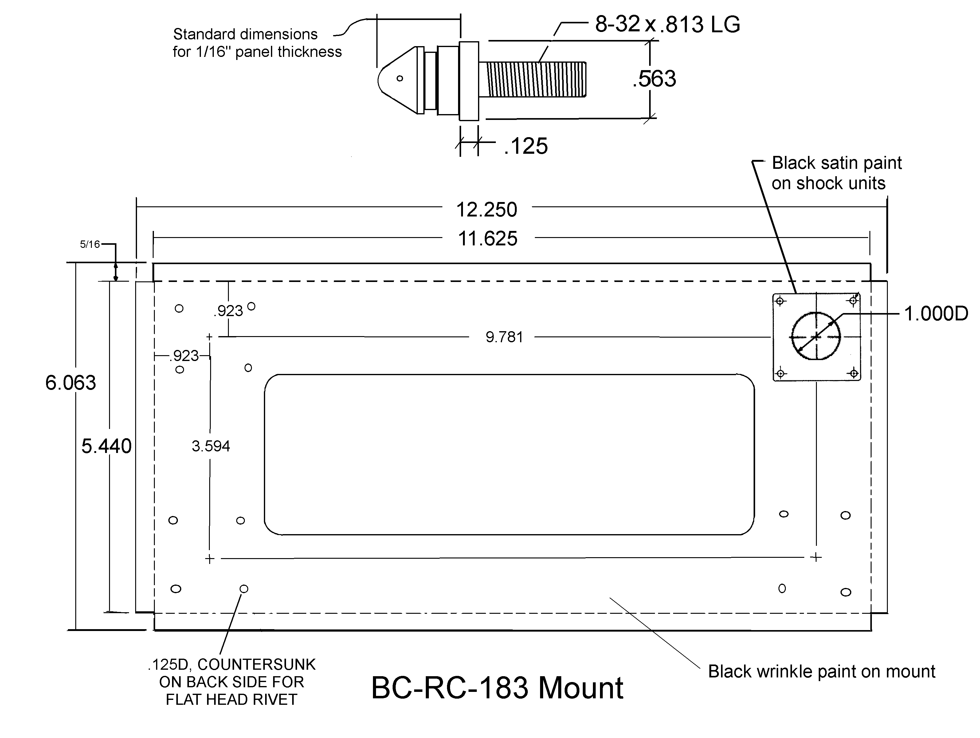
You can see the mount under this oscillator in the photo from the manual shown above. Using the manual and for some dimensions simply scaling other dimensions, I came up with the fabrication sketch shown below.
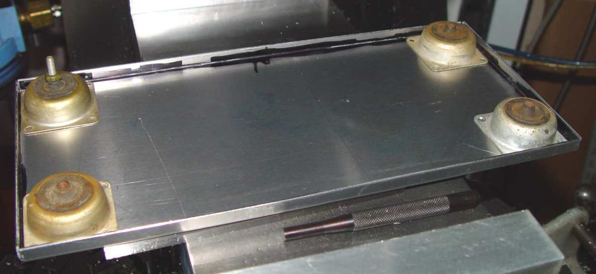
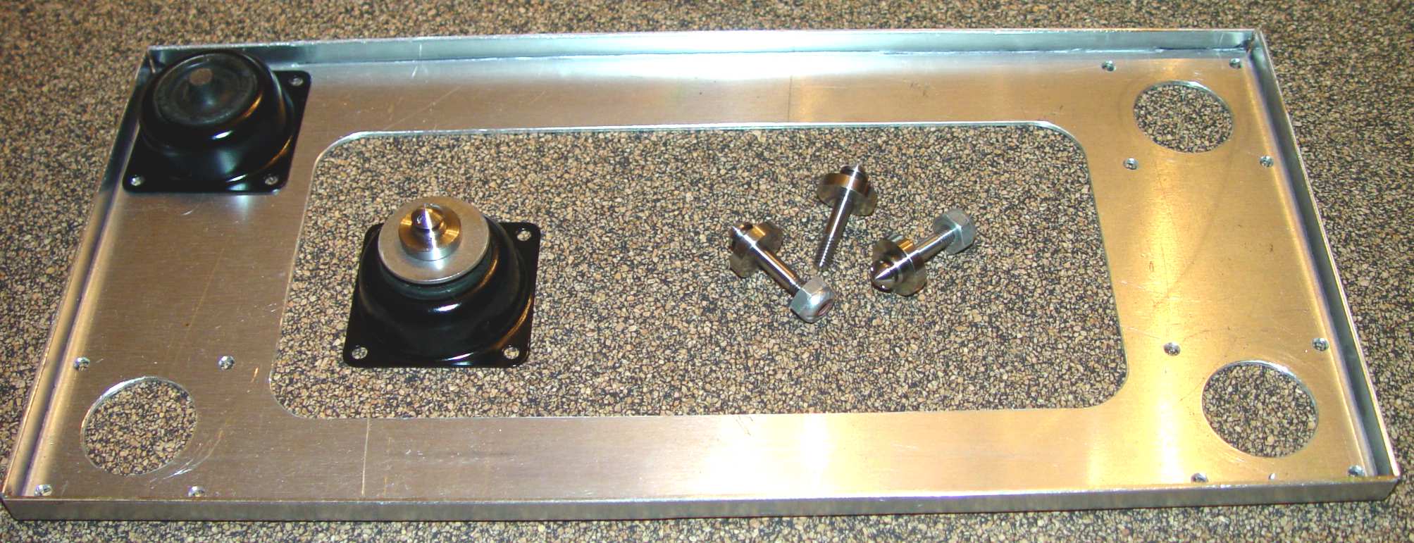
The photo below shows the first step in fabricating this mount. The shock units are actually miniature versions of the large mounts usually seen on WWII sets. The Lord plate form mount part number is 100PL-2, and the military nomenclatue is AN8008-D2. Its metal base is 1.25" square.
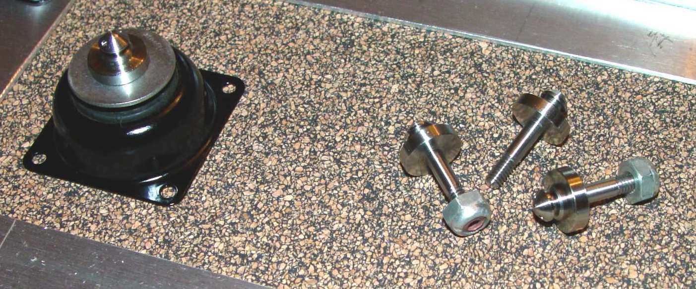
Below is the mount and snap slide posts after machining. There is a 1" diameter washer shown under the post on the shock unit that was often included on WWII mounts to prevent the set from tearing the rubber insert in a hard landing, but after closely examining photographs of the unit in the manual, I decided to omit it in the final assembly.
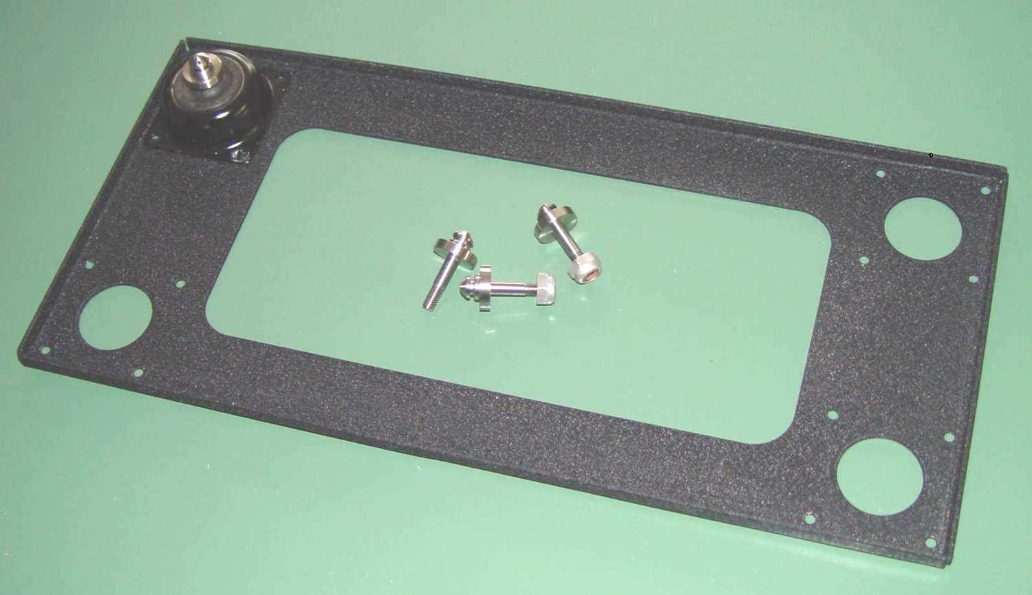
Almost there...only the rivets need to be sized and set on the shocks with a rivet squeezer. Like most folks, I don't have a zillion rivets of different sizes available to me like the original manufacturers did, so I'm relegated to shortening a longer one to the correct size. Because of the pre-WWII design penchant for forming round heads, a hemispherical die is needed, along with some experimentation on the visible length above the mounting surface. The usual rule of thumb of 1.5 x the rivet diameter doesn't hold very well for a hemispherical head. Running through a few test lengths produced a figure of .75 x rivet length for a decent looking head. The snap slide posts are made from stainless steel, since the original brass type would have to be nickle plated and it was just as easy to make them from stainless to eliminate that step.
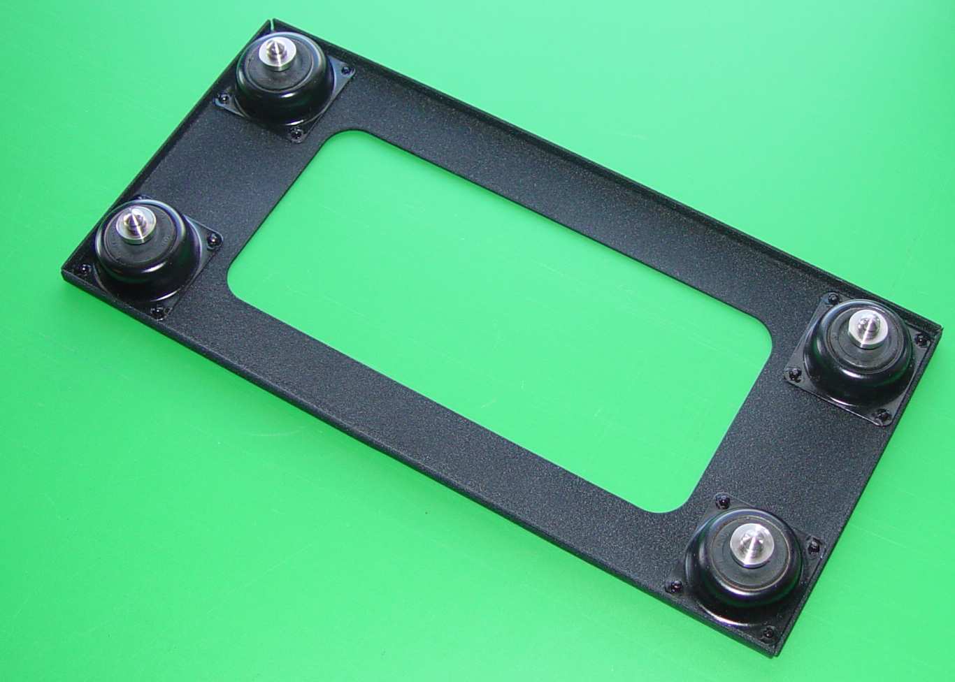
Below is the completed mount.
Finally, a photo of the completed mount with the oscillator installed.