Original MT-284/ART-13 mounts
For some reason, one of the most difficult peripherals to find for the rather prolific ART-13 equipment suite is the mount. Some sort of mount is absolutely essential, because the transmitter has a carefully designed heat convection system that requires about an inch and a half of space underneath the transmitter for cool air to enter. A good friend of mine had been looking for one for a long time, so I took a look at my original MT-284 mounts and decided that a reasonable facsimile would be feasible without too much effort. The stumbling points in accurate reproduction are the base, which requires special dies and a large press to form into its transmitter-sized shape, and the intricate intermediate shock layers which also require spot welding little retainer cups onto the top and bottom assemblies for its multi-layer design, not to mention the difficulty in finding the unique rubber pads that provide the cushioning.

Faced with that complexity and in thinking about the problem a bit, I decided that a fairly decent replica from a visual perspective wouldn't necessarily need real resilient shocks - the original mounts for the 1940 ATC (renomenclatered AN/ART-13 in 1943 under the A/N system introduced that year) were simply stainless steel rails, which often required an external set of shocks between the rails and the airframe if vacuum tube life was to be reasonable in a vibrating piston powered aircraft. Now, the most common integral aircraft shock mount design for most of the war used four to six rubber insulated shock "units", or "towers" (of the type produced by companies like Lord and Barry) that were mounted on two 1/16" thick aluminum "shoes", or channels, made on a sheet metal brake. That simple shoe approach is the genesis for this pair of mounts. No rubber is used in the assembly, and fabrication can be accomplished with a lathe, a sheet metal shear and brake, and a drill press (okay, I did use a milling machine, but it's mostly because I don't have a drill press...heh.)
The basic material for this mount is .063" 5052-H32 aluminum, available in small quantities on ebay for a reasonable price. 5052 is a soft annealed aluminum that I like to use for projects that require bending without cracks. The more common 6061 alloys can be bent as well, but they don't like small radii...they will frequently stress-crack along the bend line somewhere. Because of its softness, 5052 is a rather gummy material to drill, but a spritz of WD-40 works fine to keep drill flutes clean.
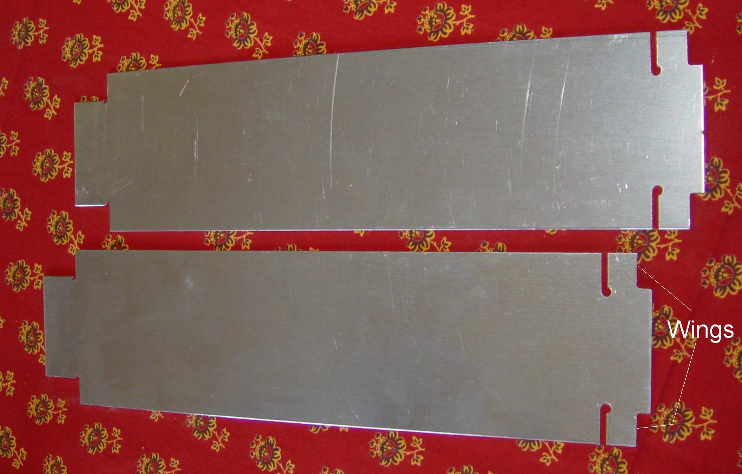
The top of the mount is another "shoe", but has to mate with female shoes that are part of the transmitter. The photo above shows how the 3 5/8" x 14 1/4" patterns look when laid out and cut prior to bending.
Sketches of the piece parts are located here.
Once the pieces in the photo above have been fabricated, the bending must be done in a preplanned sequence. The tabs marked above as "wings" are the critical bends from a dimensional standpoint, and they have to be bent first. Then the long side rails must be bent, stopping at a 78 degree angle. Then the front tab with the two "wings" must be bent, allowing them to fold up into place touching the side bends - a pair of rivets or flat head screws then holds them together. The rear tab is bent last. I used a combination of two types of brakes to make this easier - a finger brake (sometimes called a pan and box brake) and a press brake. Each has its advantages for particular bends and configurations.
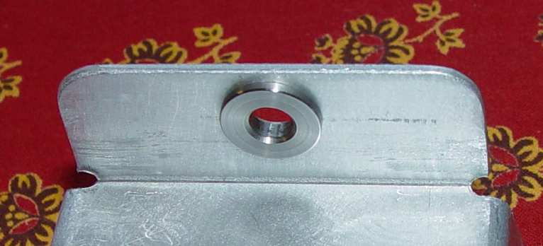
It is easier to drill the rear hole last by placing the shoe on the ART-13 transmitter rail and marking the locating post on the shoe (you do save some old typewriter carbon paper for jobs like that, don't you?) Minor differences can be corrected with a rat tail file and then cleaned up with a tapered reamer. To preserve the original look from the top, I elected to install stainless wear rings for the retaining posts on the rear of the transmitter that were designed into the original mount, but for most purposes it probably isn't needed. The original mount also uses a strengthener plate underneath, but that is because it has to withstand severe turbulence and hard landings...factors that the ground based application will never face.
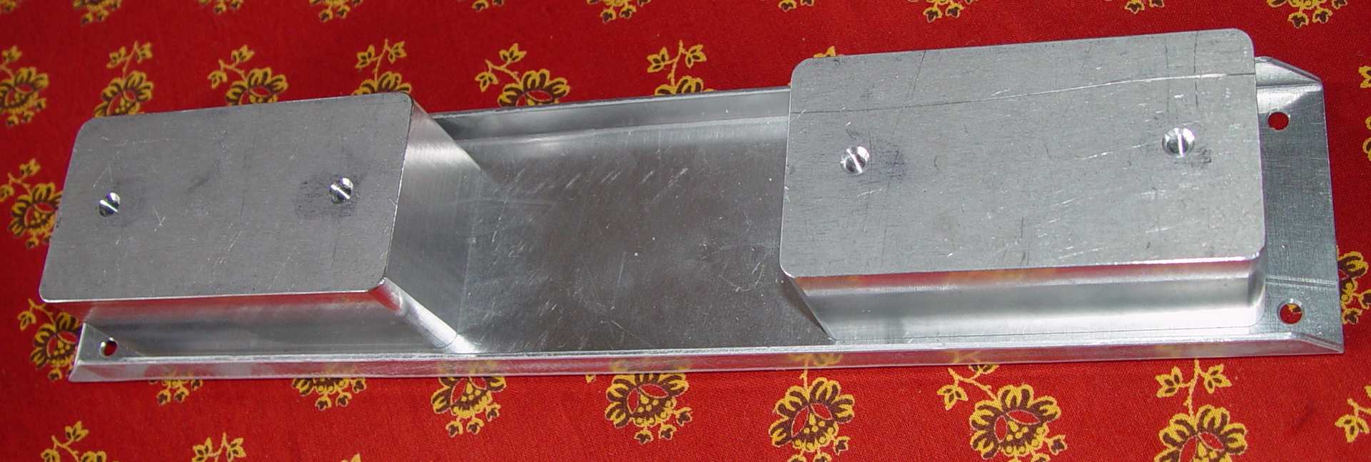
As mentioned above, the bottom shoe is a conventional channel design used on dozens of different WWII aircraft radio mounts. The spacers can be made in several ways, including bending up some 1.5" channels or using extruded aluminum channels of the same dimension. I had some solid 1.5" aluminum plate in the junk pile, so it was easier to simply use that.
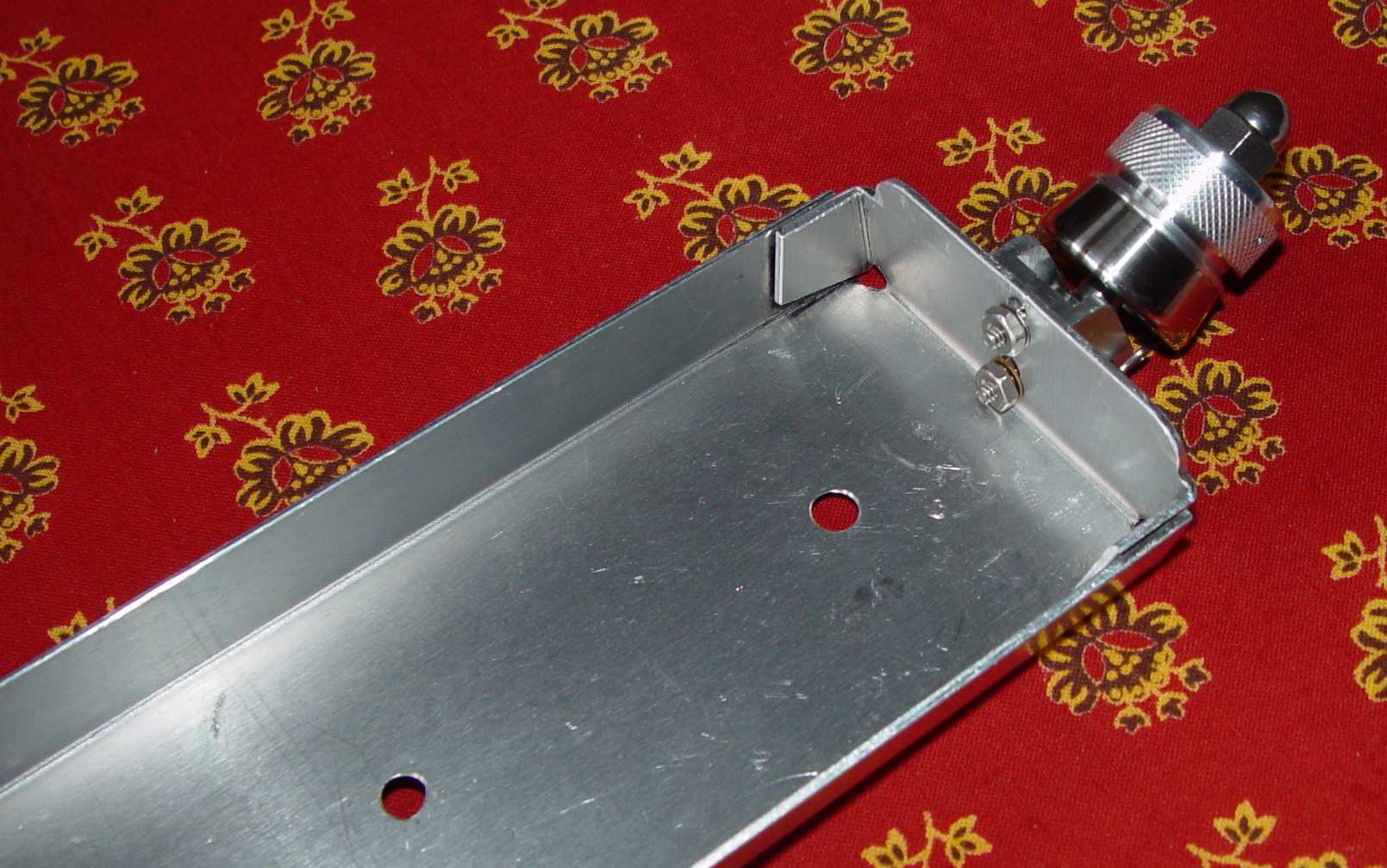
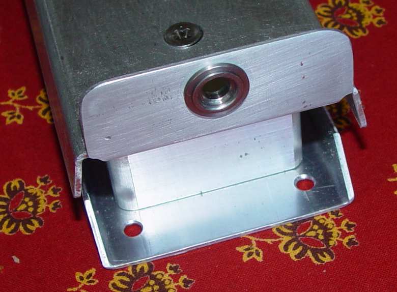
Next step is to make the parts that provide most of the authentic ambiance of the mounts - the front retainers.
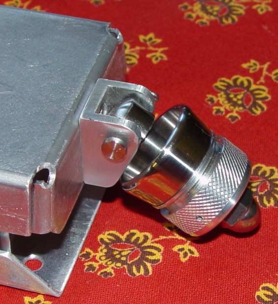

The swivel mount for the thumbwheel and retainer on the original mount is made from 3/16" thick stainless steel. If you have ever tried to form that thickness of stainless into a small channel shape, you will know that it is like trying to straighten a bumper from a 1940's automobile...you need pretty humongous tools (or a really big hammer and die) to do it. I replicated the shape of the original with aluminum - a lot easier to work. Both the aluminum knurled thumbwheel and its stainless clamp adapter are made from 1" stock and match the original. For the terminally obsessive like myself, you can finish the thumbwheel with a pair of 1/16" diameter safety wire holes drilled at 45 degrees through the knob, but to do it most easily you should have an indexing collet fixture so that you can rotate the thumbwheel precisely 180 degrees for the second hole. Note that it is better to spot drill these from the front with a small center drill, followed up with a 1/16" drill, as doing it from the periphery will often result in the holes emerging at slightly different radii from the center post where it is most visible...an unsettling result for perfectionists... The threaded swivel itself is a 1/4-28 threaded stainless rod with a hemispherical end that has flats milled on the sides, but there are a number of alternatives for achieving the same effect. A stock 1/4"-28 acorn nut completes the assembly. Anyone needing a sketch of these parts should send me an e-mail - I haven't had time to make them as of this writing.
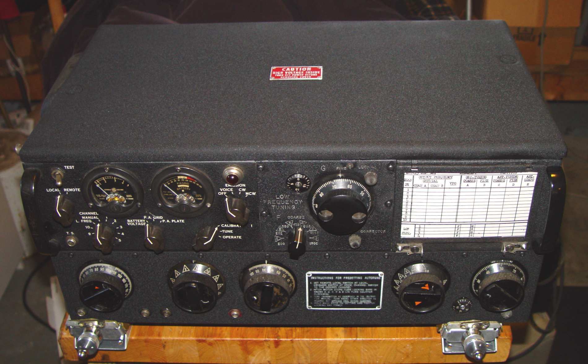
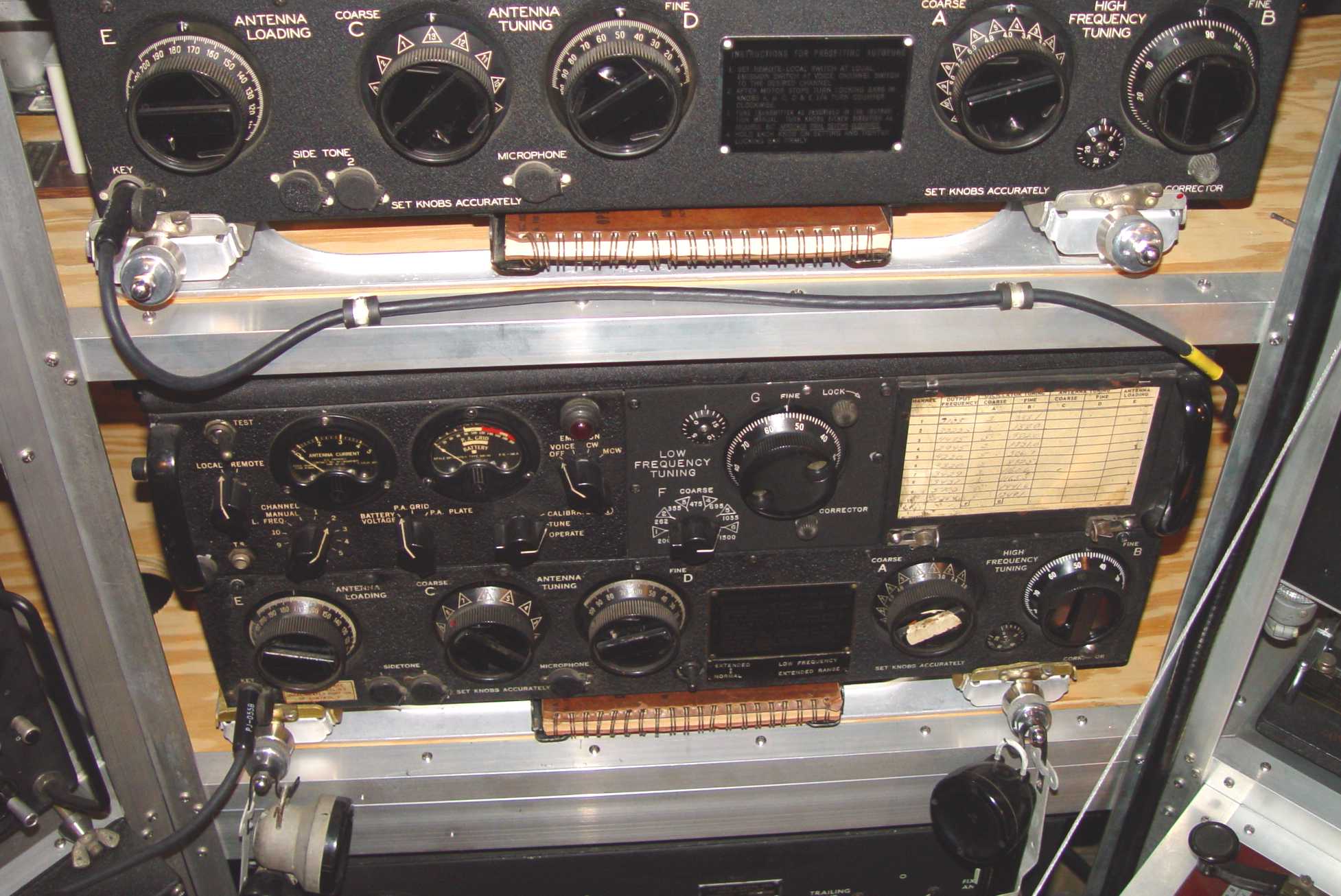
The result shown below with the transmitter on top is a relatively pleasing picture compared with mounting the transmitter on wooden boards or the other work-arounds that are usually employed, and provide the same ease of sliding these heavy transmitters onto a spot on your operating desk. If you don't have the tools required, find a friend that does and bring over some suitable encouragement.