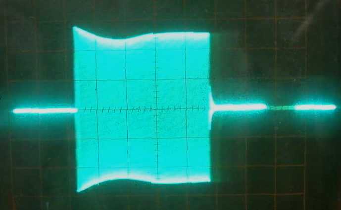
Final CW Note after increase in C-55 capacitance to 20uF
from its original 1.2uF. Note the increase in envelope period.
Ignore horizontal scale - the keying period had to be adjusted
slightly for a steady photo.
During a recent SCR-274N restoration project for a club event, a problem was discovered that some of you may find interesting or helpful should you ever run in to it. The project required that the set be fully functional in its original configuration. It was a typical 2 Tx, 3Rx setup as would be found in a WWII bomber installation.
SCR-274N set restored for Rockwell-Collins Amateur Radio Club B-29 position. It included a full RC-36 interphone system.
The problem was in the keying. While listening to the CW note from the set in another receiver, it had a very bad chirp. It was really beyond chirp, it was more like a warble. It had a characteristic that reminded me of frequency shift keying. We've all been led to expect a little bit of chirp from the command transmitters, especially the 40 meter unit, but this was independent of the transmitter being used!
Upon looking at the note with a scope across the dummy load, it was evident that something was very wrong. The beginning of the note looked halfway reasonable, but the end portion had a very defined stair step shape to it before the end of the note. On a note that was keyed for 60 mS (using a contiuously running keyer), the initial 60 mS looked fine, but there was an additional 30 mS tail, where the amplitude would drop approximately 60%, and stay at that level for the additional 30mS as shown below.
Horizontal scale is 10mS/division.
I happened to check the note at two different locations in the antenna circuit, both in front of, and after the antenna relay. The signal, when measured before the antenna relay, had the step as pictured above. The signal after the antenna relay did not have it. That note looked perfect at the end but it was 30mS shorter overall, or only 60 mS in length. Obviously the antenna relay was opening before the transmitter was being cut off.
Knowing that a change in load can produce a change in frequency in a MOPA (Master Oscillator/Power Amplifier) rig, it was pretty obvious why I had a chirp. Going from loaded to unloaded is about as drastic a change in load as you can get! I confirmed the theory by leaving the antenna relay closed all the time and keying the transmitter. No step in the output, or chirp in the receiver.
By now some of you may be saying - "Okay, but the transmitted note was still only 60 mS long and the shift in frequency or chirp would not have been heard at the other end of a distant contact." True! The only reason I was hearing the shift was the fact that the receiver was in the same room. I should note here also that both the transmitter and receiver were connected to dummy loads and 20dB of attenuation was used in the receiver. That doesn't change the fact however that the output of the transmitter was being "hot switched", and in my mind at least, that was a problem that shouldn't be happening. Call it an engineer's eternal pursuit of optimization...the "right" way to do things. It also obviously has an effect on keying speeds - the manual says 12 WPM is a recommended maximum. Now, the $64 question about the waveform was, WHY?
When you look at the two primary relays involved, K-52 (H.V.) and K-55, (Antenna) it's hard to imagine K-55 opening before K-52 because the throw of K-55 is so much farther, even on the opening of the contacts. My first idea was to unhook the little extension spring from the arm of the relay to slow down the opening of the contacts. That didn't make any noticeable difference in the timing on the scope!
After a lot of head scratching and theories about corroded hinge pins and the like, and ruling out possible mis-wiring or faulty components, I realized that about the only thing left was just plain old interaction between all those relays being keyed at the same time. If you look at the entire keying circuit, these two relays are not the only ones being keyed. There's the sidetone relay, and the three muting relays in the receiver rack too. Each of the relays has a magnetic field that collapses upon release of the key. Collapse of that field attempts to keep the current flowing through the coil in the same direction. If there is no return path through which the current can flow, then the collapse occurs in the shortest possible time, dictated by the mass of the armature and the return spring constants. If there is a return path for the current, then drop-out of the relay is slowed down, roughly in proportion to the amount of magnetic energy contained in the field. Most of the time this interaction doesn't cause any problems, but in this case, it clearly affected the CW note! By setting up the scope in dual channel mode and comparing the timing of various relays, it was confirmed that the relays do interact greatly with each other. Watching the timing of both K-52 and K-55, and simply unplugging the receiver rack for example, the timing difference could be cut by as much as 75%!
I was able to add a capacitor type 'off-delay' circuit that would hold the antenna relay in slightly longer and solve the problem with the CW note, but with a little technical consultation from Mike Hanz, we were able to come up with what we thought was a better approach. Mike didn't feel like the relatively large electrolytic capacitor required would stand the keying shock for very long and would eventually fail. He suggested that we isolate each of the relays from each other with diodes as in the simplified diagram below. This is done by connecting a diode in series with each key line, with the anodes connected to the negative coil terminals. What this accomplishes is to isolate the back emf that is generated upon collapse of the field in each of the coils when they are de-energized so that they will not backfeed or otherwise interact with the other relay coils. The diode has no effect on the rise of the field when the key is closed, but speeds up the dropout times to roughly what they would be without the relays being paralleled.
The easiest way to do this is to install the diodes in the keying lines going to each major component by soldering them to the pins of the connectors inside the modulator. This way, the mods only occur in one piece of equipment, not all of them. Another option is to hide them in the cable bundles, but in my case the cables were already fabricated. Yes, I know, this may bother some of you who pledge no modifications of any sort, but the fact is that this particular modulator already had modifications made to it that I had to back out, and there were also some bad capacitors and resistors that I had to replace at any rate, so it isn't as bad as it might seem. It is, after all, a working set, not a museum piece. This modification involving the adding of diodes is very reversible. Even the other mods shown in the photo below are easily undone if the proper replacement is later found. By no means were any additional holes drilled! The purpose of this piece is not to suggest modification, but rather to inform the reader of a potential problem and suggest a possible fix. Below is a photo of the tacked-in diodes.
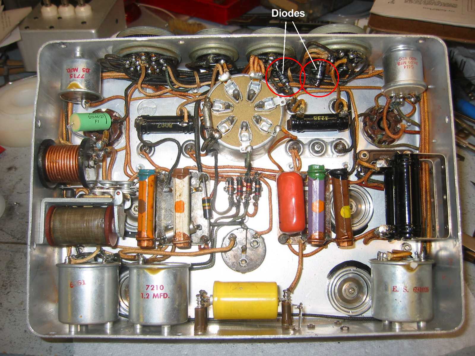
The isolation diode for the antenna relay is placed in the key line going to the transmitter rack, since the antenna relay is keyed through that rack connector. Likewise for the key line going to the receiver rack for the muting relays. The only relays left that need isolating are the HV and sidetone relays in the modulator. The remaining relays (K-53 Tx select, and K-54 Tx output) don't need isolation as they are only actuated when the Tx control box is switched to that transmitter. They remain energized until you switch to a different transmitter.
Below is a picture of the envelope after the isolation diodes were installed.
The damped sine wave modulation shape you see at the beginning of the note above is due to the resonance of L-51 and C-55 when the B+ is initially popped onto it. The subsequent ripple is of course a small amount of dynamotor ripple inadequately filtered by that same L-C pair. They were both addressed later simply with additional capacitance, though it is interesting to note that the coil and capacitor were both within published tolerance.
Final CW Note after increase in C-55 capacitance to 20uF
from its original 1.2uF. Note the increase in envelope
period.
Ignore horizontal scale - the keying period had to be adjusted
slightly for a steady photo.
The final CW note obtained after all this work is still not quite what you would consider textbook shaped keying, but I wanted it to retain a little character at least. I wanted it to sound like a real boatanchor, not a Kenwood or Icom. :-)
Now, the only remaining question in my mind is this.....Did the 274N always have this characteristic on CW? I really can't see how this could be something that develops with age. A coil is a coil is a coil, even if the varnish on the wire is a little dried and cracked. Mike checked out several of the modulator, receiver rack, and antenna relays he had in storage and discovered some small (less than 10%) differences in relay timing between those of a given type, but all were consistent enough with the ones in my BC-456 to reflect the same potential for creating the chirp, depending on how they were paired up in the lottery of manufacturing. Obviously, the chirp was accentuated by having the test receiver and test equipment so close to the set, but in the spirit of exploration, it seems that an interesting set of compromises must have been made in the original design.
Hmmmm.......
SteveWilliams
KB4DMF