ARC 7369 (Signal Corps I-84-A) Receiver Test Meter
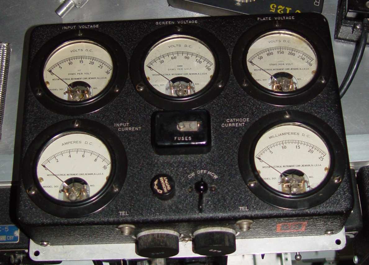
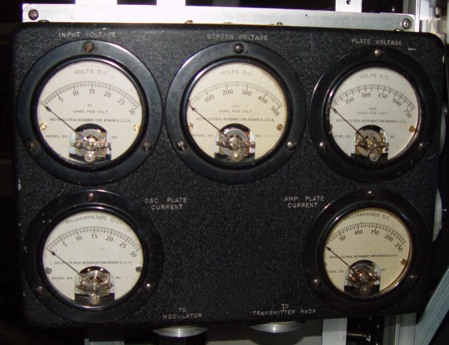
There was an interesting progression of test meter units for the ARC command set series over the war years. The first test set, the ARC 7369, was produced for the Navy RAT/RAT-1 set in 1939 and production continued through the end of the war. The 7369 was intended only for testing receivers, but in 1940 a new set, the ARC 7544, was also introduced with the Navy ARA/ATA set designed for use with the transmitters. The two test sets were composed of a pair of aluminum boxes with five 3.5" meters mounted on each box. In the case of the 7369, some mode switching ability and gain adjustment for the receivers was included.
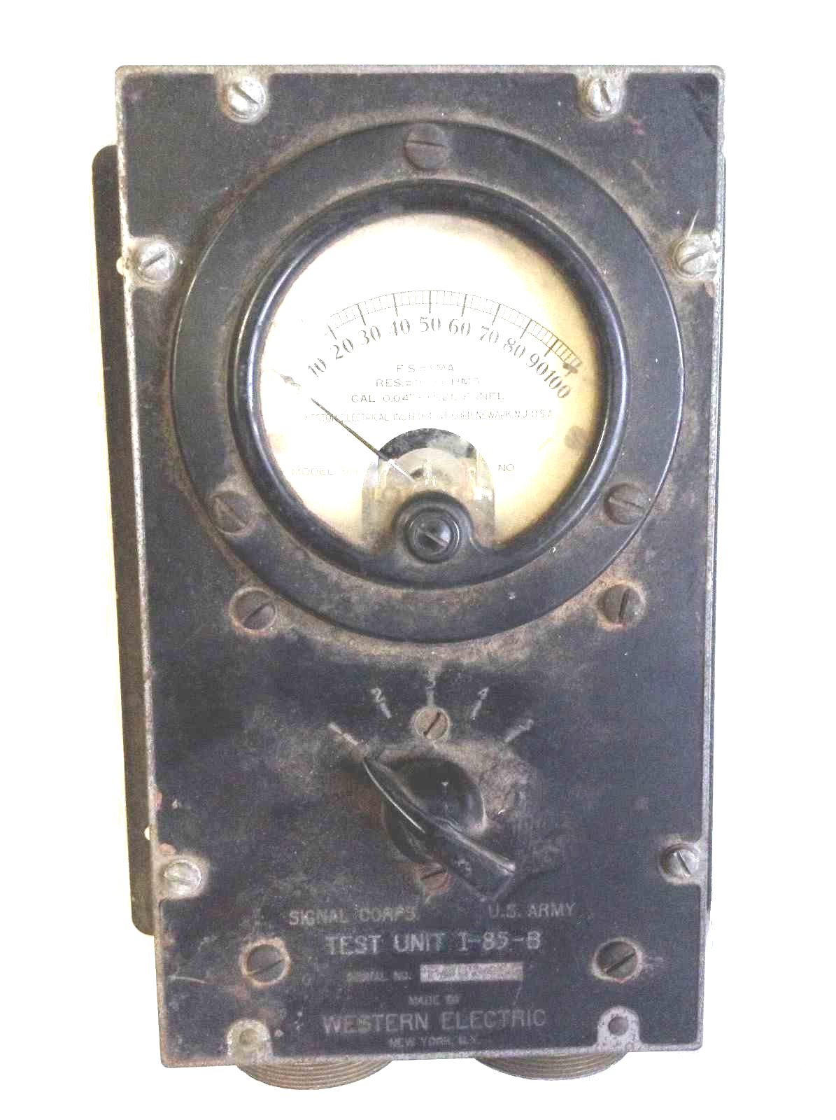
The Signal Corps adopted these test sets with the initiation of the SCR-274N contracts, but relabled them in their own quaint way as I-84-A (part of RC-54-A) and I-85-A (part of RC-55-A) (RC = Radio Component, which defined a complete set of equipment, in this case all the cables and ancilary instruments necessary to provide a complete test capability). Western Electric even gave them Western Electric part numbers to confuse the unwary.
Fast forward to the last of the wartime command set series - the AN/ARC-5. The five meter sets were still being made, but labling went back to ARC numbers rather than military nomenclatures. For good reason, they retained the old 7369 for the receiver set but designed a modified one - the 9556 - for the transmitter set. The only difference between the 7544/I-85-A and the new 9556 are new connectors requiring a 9377 mate and revised wiring of those connectors. For example, pin 4 in the 7544/I-85-A units is ground, while in the new 9556 it is +28 volts. It was a change forced by the new (and different) connectors on the rear of the AN/ARC-5 transmitters. Obviously you can make either one work on any of the sets by adjusting the mismatch with two sets of connecting cables, but it bears checking if all you have is one.
To help sort this out, details of these two test sets for each of the command sets are shown here. Again, note that there is only one receiver test set to worry about, while there are two (with three nomenclatures) for the transmitters.
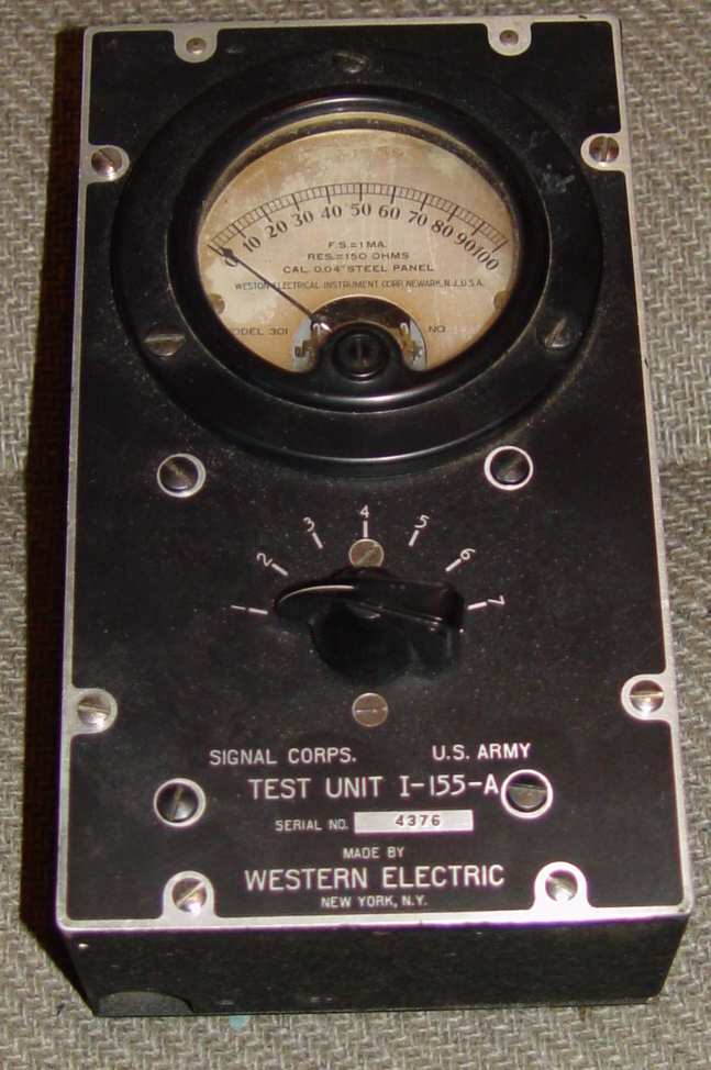
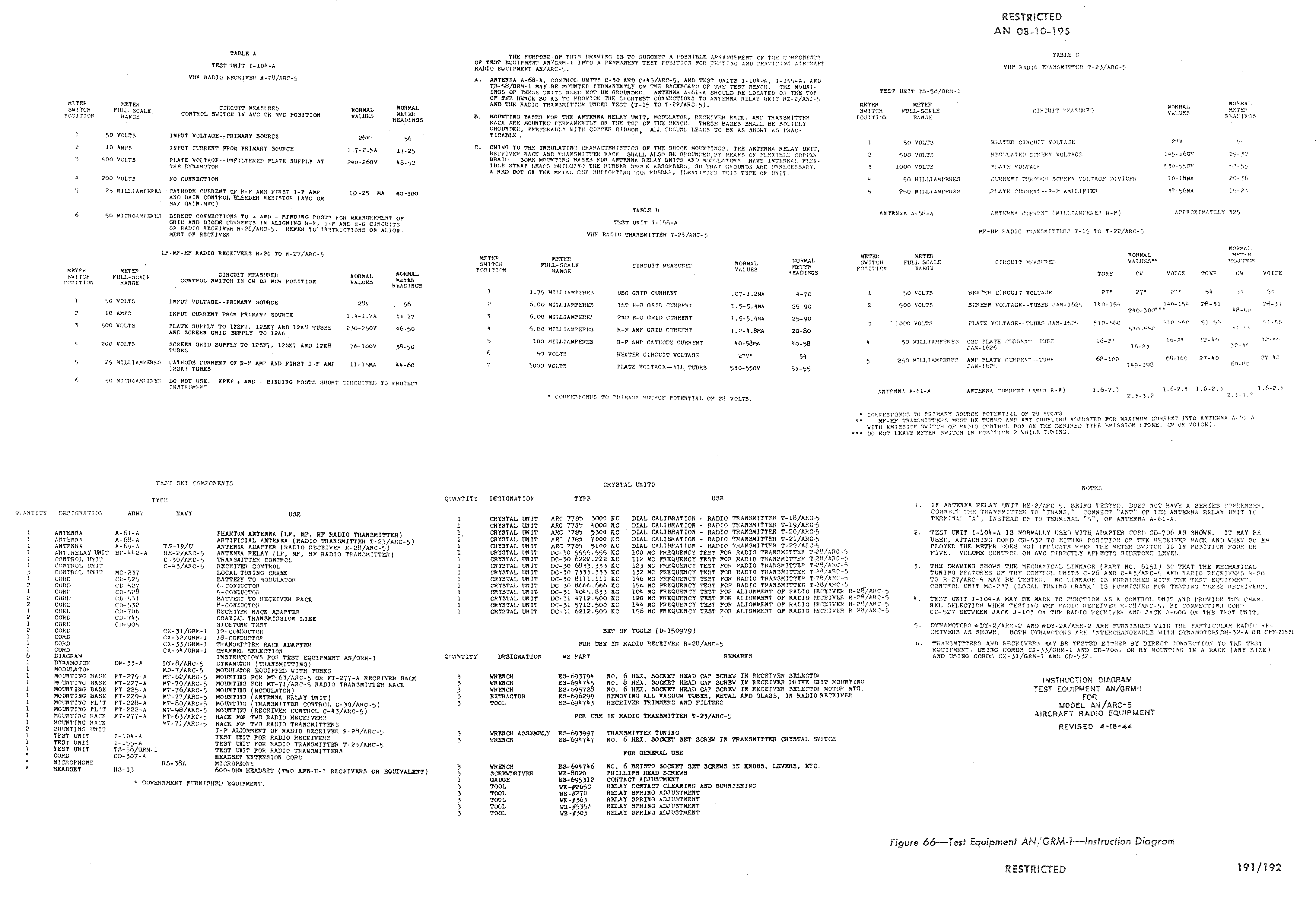
The problem with these rather elegant test suites was twofold - cost and scarce resource use. Ten sensitive, calibrated meters in desperately short supply were required for each complete setup, a resource that had the Federal government calling for hams and radio enthusiasts to voluntarily send in meters that they were not using. With a war on, it was soon decided that a simpler way of testing the command sets was needed for flight line and field use. This is where it starts to get a little more complex, because the introduction of the AN/ARC-5 VHF equipment in 1943 required a slightly different set of test boxes. As a result, the Signal Corps developed two different sets for the VHF and HF requirements; the IE-35-A, which contained an I-155-A test meter designed only for the T-23/ARC-5 VHF transmitter, and the AN/GRM-1 (a label caught up by the introduction of the JAN nomenclature system), which could service both HF and VHF command sets. Naturally, the GRM-1 also had an I-155-A listed in its compliment.
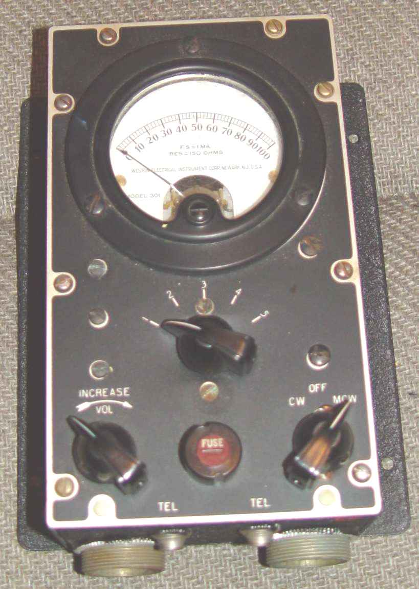
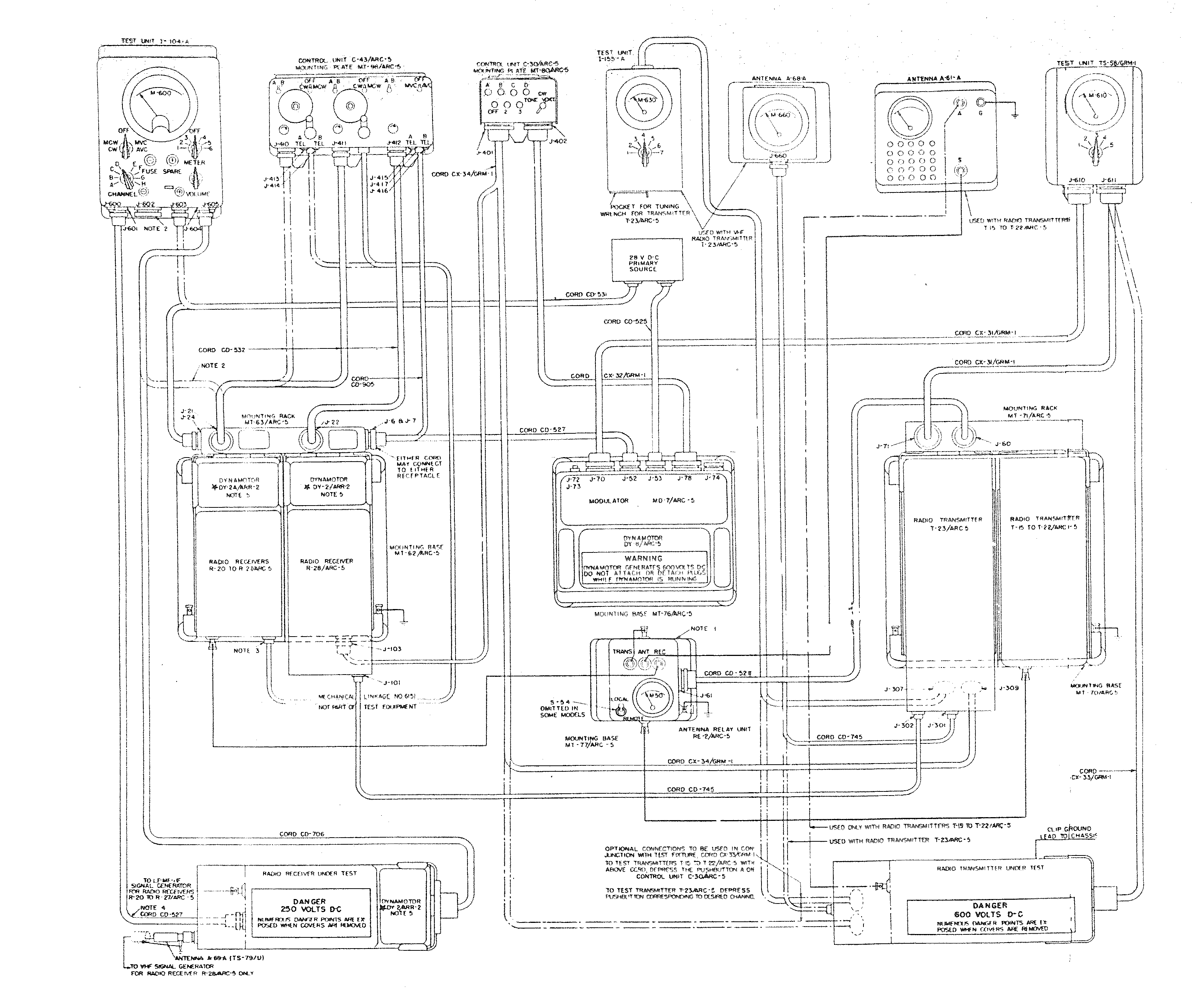
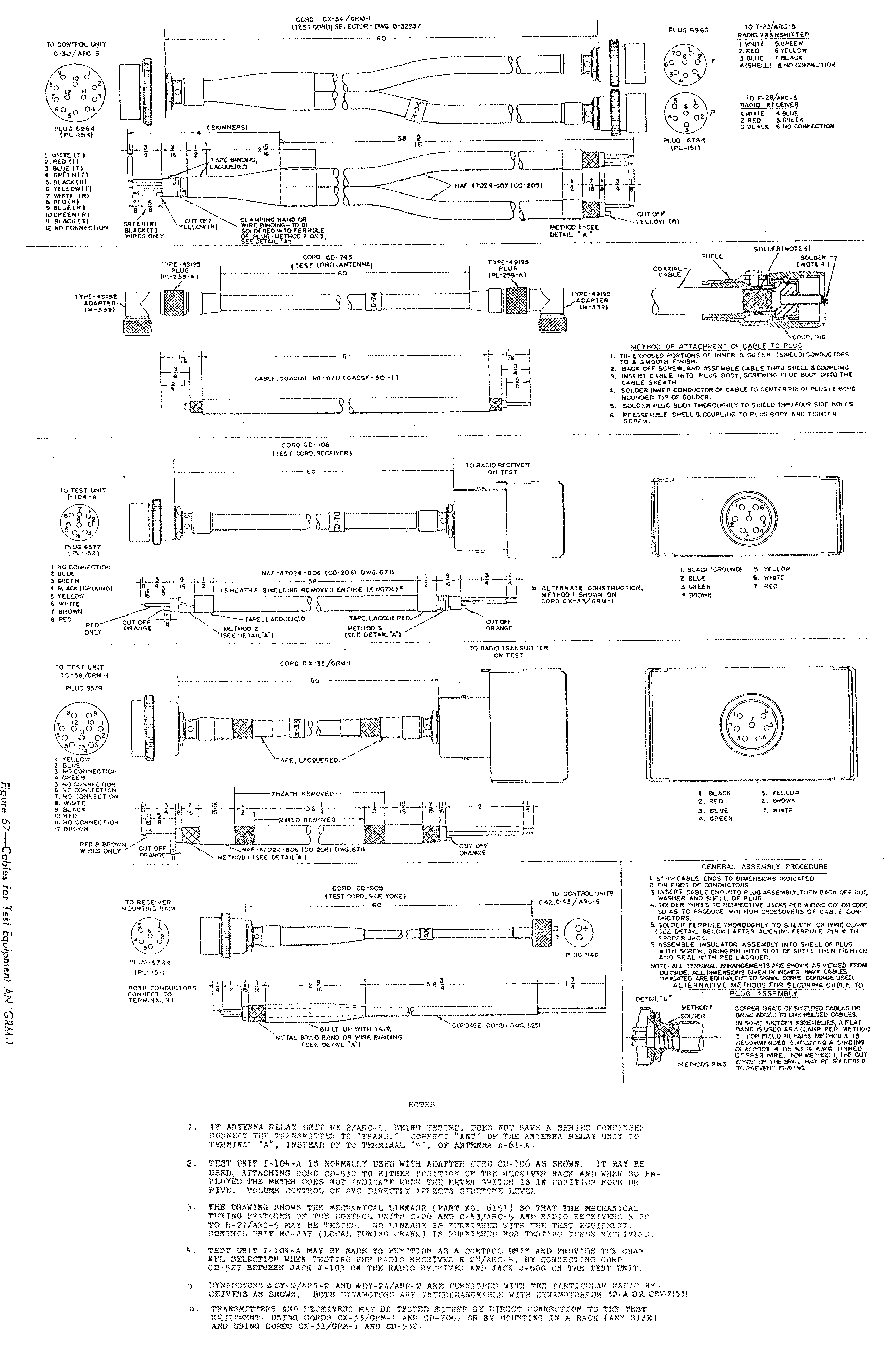
It appears that they also produced an I-84-B for receiver testing during a short period of time before or perhaps during the initial deployment of the GRM-1 with its later I-104-A combined transmitter/recever test set evolution. There are mentions of an RC-54-B and RC-54-C in the later SCR-274-N manuals, but no corresponding set of instructions for their use. The I-84-B was a single meter approach that provided the same functionality, if not the ability to watch multiple parameters at a single time. Unfortunately, the receiver metering sets all require the use of a connector that plugs into the rear connector of the receiver. There is no way to measure all the parameters through a typical receiver rack without a modification of some sort. See notes 2 and 6 of the GRM-1 cabling diagram below. In contrast, all the transmitter test meter designs permit leaving them in-line for a complete operational system if desired.
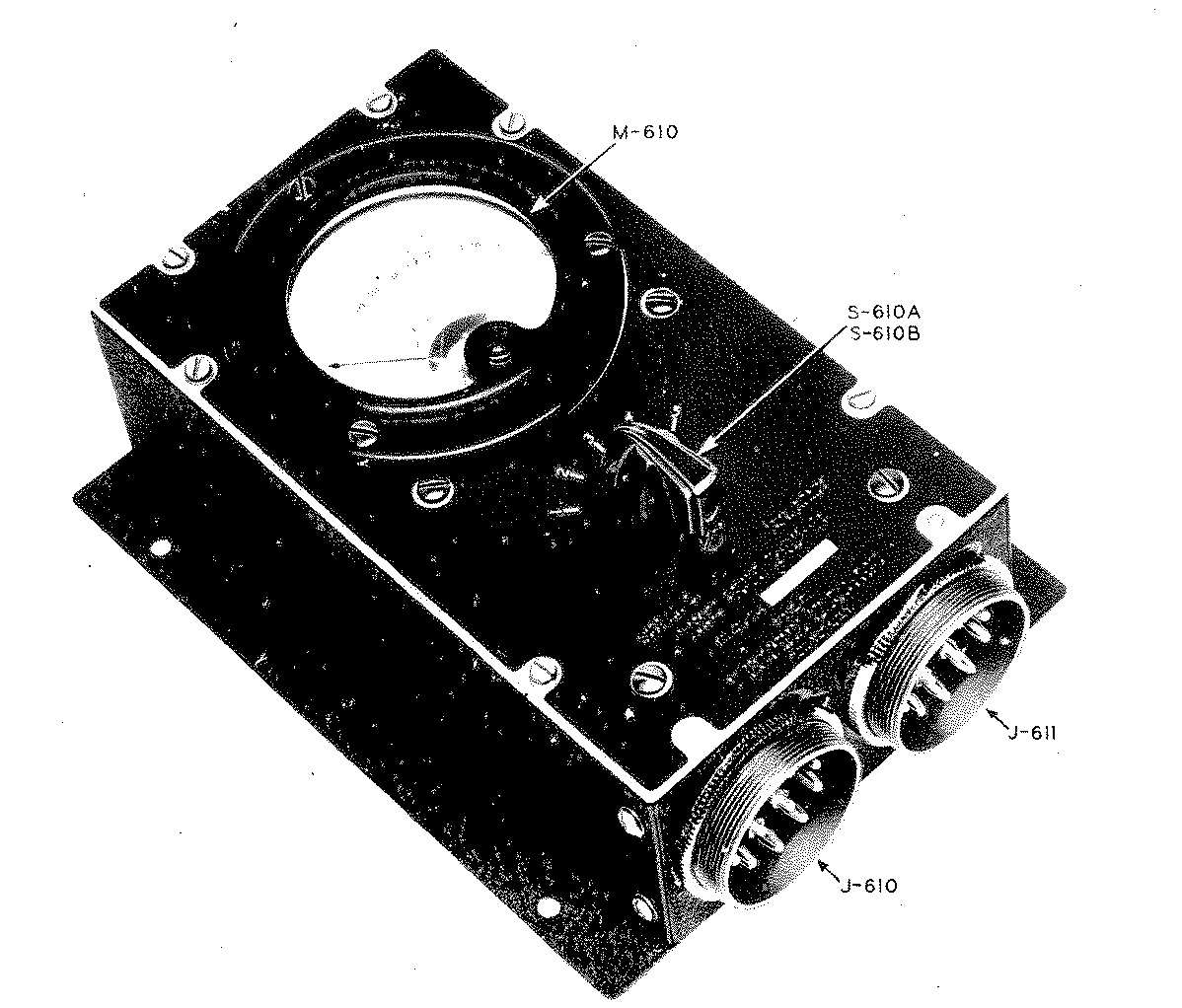
To cover the transmitters, there was a corresponding I-85-B (formally labled in the manual as the TS-58/GRM-1, shown below.
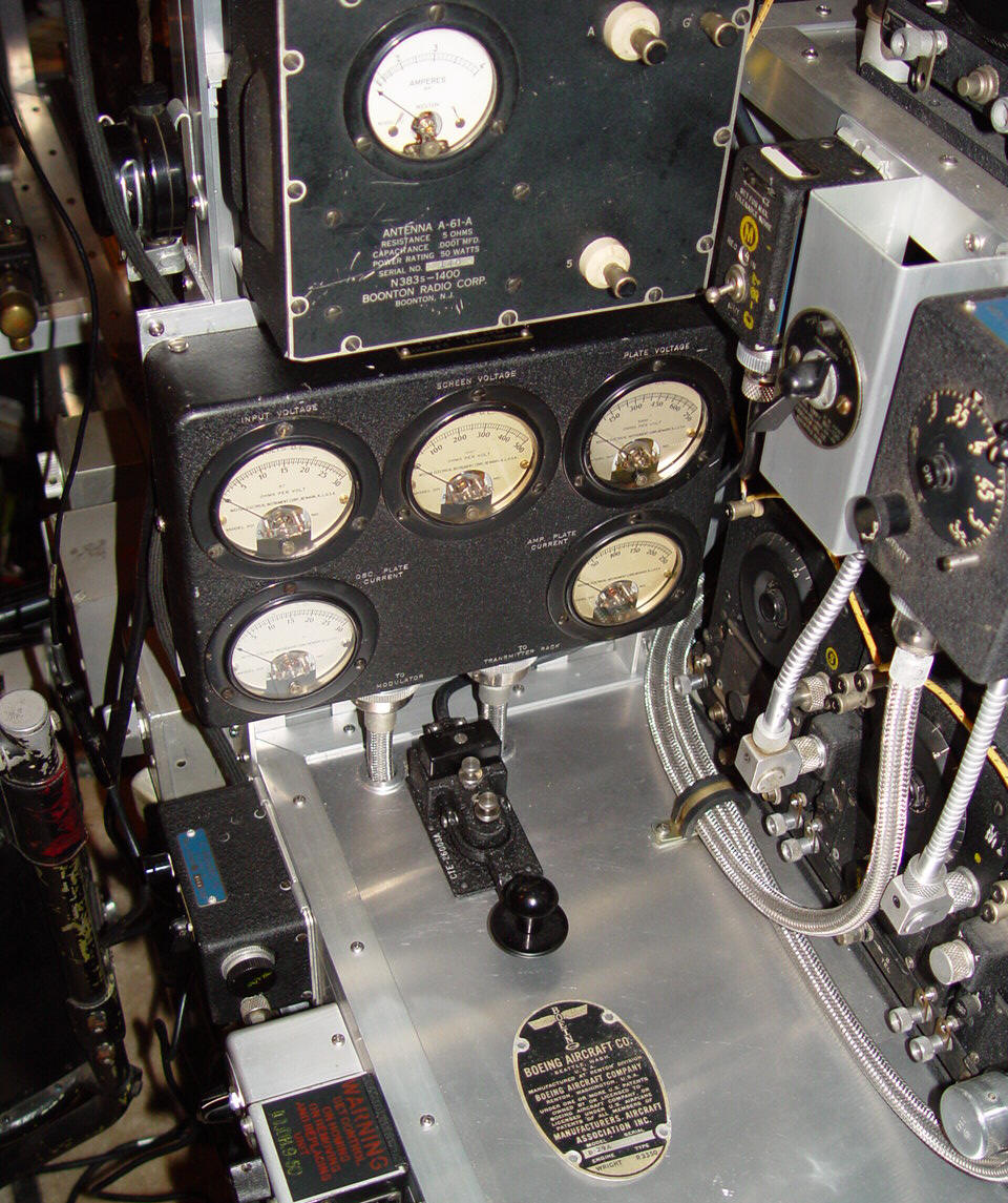
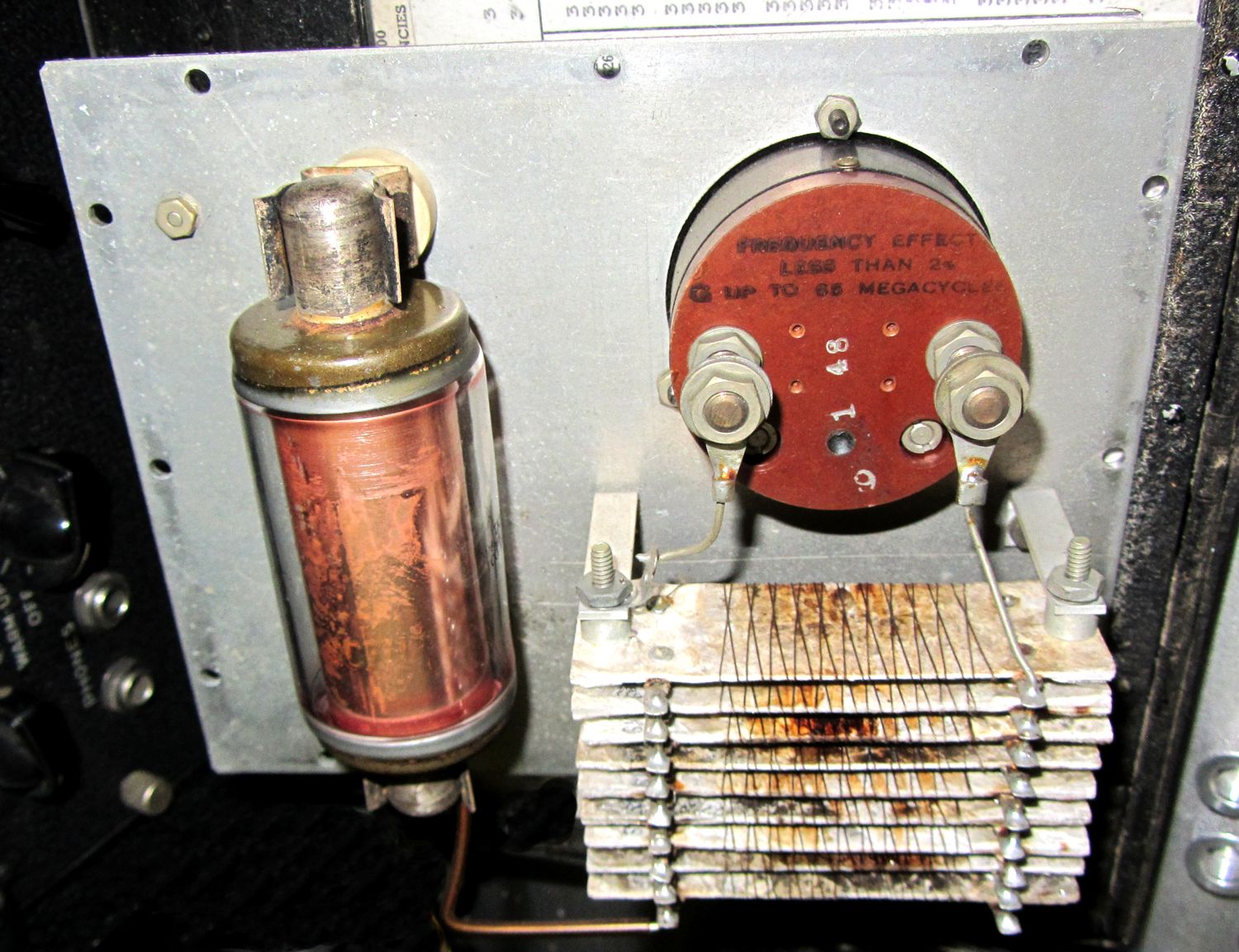
Part of the GRM-1 included a phantom antenna, sometimes called a dummy load, handed down from the SCR-274-N days and still called the A-61-A. It provided a five ohm non-inductive load, along with a series 100pF vacuum capacitor to simulate typical aircraft antenna characteristics. A photo of a rare Boonton Radio version of this load from an earlier Navy contract is shown below, along with an I-85 transmitter test set. Note the 50 watt power rating, along with the 0-4 RF ampere meter with an internal thermocouple.
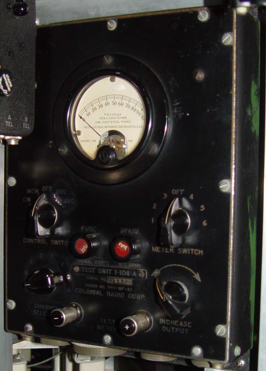
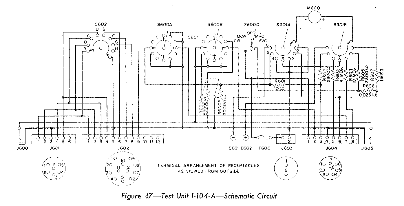
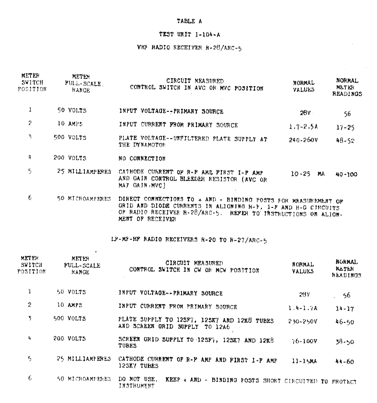
The introduction of the VHF ARC-5 set was in essence a stopgap effort by Western Electric to provide an alternative to the essentially British developed and Signal Corps repackaged SCR-522, and the Signal Corps had plans for its replacement even as it was being produced. Those plans reached their culmination in the AN/ARC-3 about the same time as the GRM-1 test set was being developed, because the GRM-1 has the capability of servicing both the ARC-5 and the ARC-3 equipments. The functionality of the I-84-B and the TS-58/GRM-1 was incorporated into the I-104-A, and first five of the six positions on the meter switch correspond to the same positions on the I-84-B. The circuit diagram of the I-104-A is shown below, along with the meter switch positions and functions.
ARC eventually produced commercial test equipment for their postwar sets, including a nifty metered power supply and a couple of variations of the I-104 that were redesigned for the VHF channelized transmitters and receivers, but they were never in the mold of the beautiful "five meter" sets.