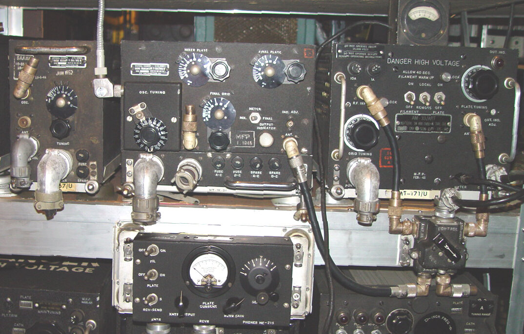
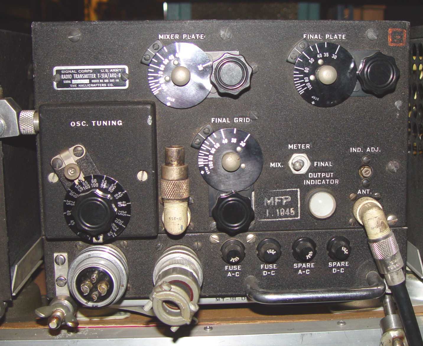
The ARQ-8 jammer is a good example of rapid response to a threat. Hastily put together to deal with German glide bomb successes in the Mediterranean, the R-58/ARQ-8 and T-51/ARQ-8 showed immediate promise in dealing with the problem. It followed the trend at the time of using a DSBRC approach to widen the jamming bandwidth, and employed the master oscillator of the transmitter as the LO for the receiver on the left to ensure locked-in jamming. It was tuned +/- 2.5MHz about a predetermined center frequency using the C-93/ARQ-8 control box on the bottom. The "tuning meter" above the amplifier on the right is a TS-60/U used to measure plate current of the two 4E27 push-pull amplifier tubes. It was used on virtually all of the jammers as a tuneup tool.

The power output of the 829-B PA tube was about 20 W, but the lack of numerous jamming aircraft to orbit Allied shipping suggested even more power was required. The AM-33/ART below was the answer to that need. The broadband characteristic of the output spectrum wasn't amenable to more conventional amplifier designs, so the designers chose to use a Class B linear amplifier approach - long before the use by radio amateurs of the technique for SSB.
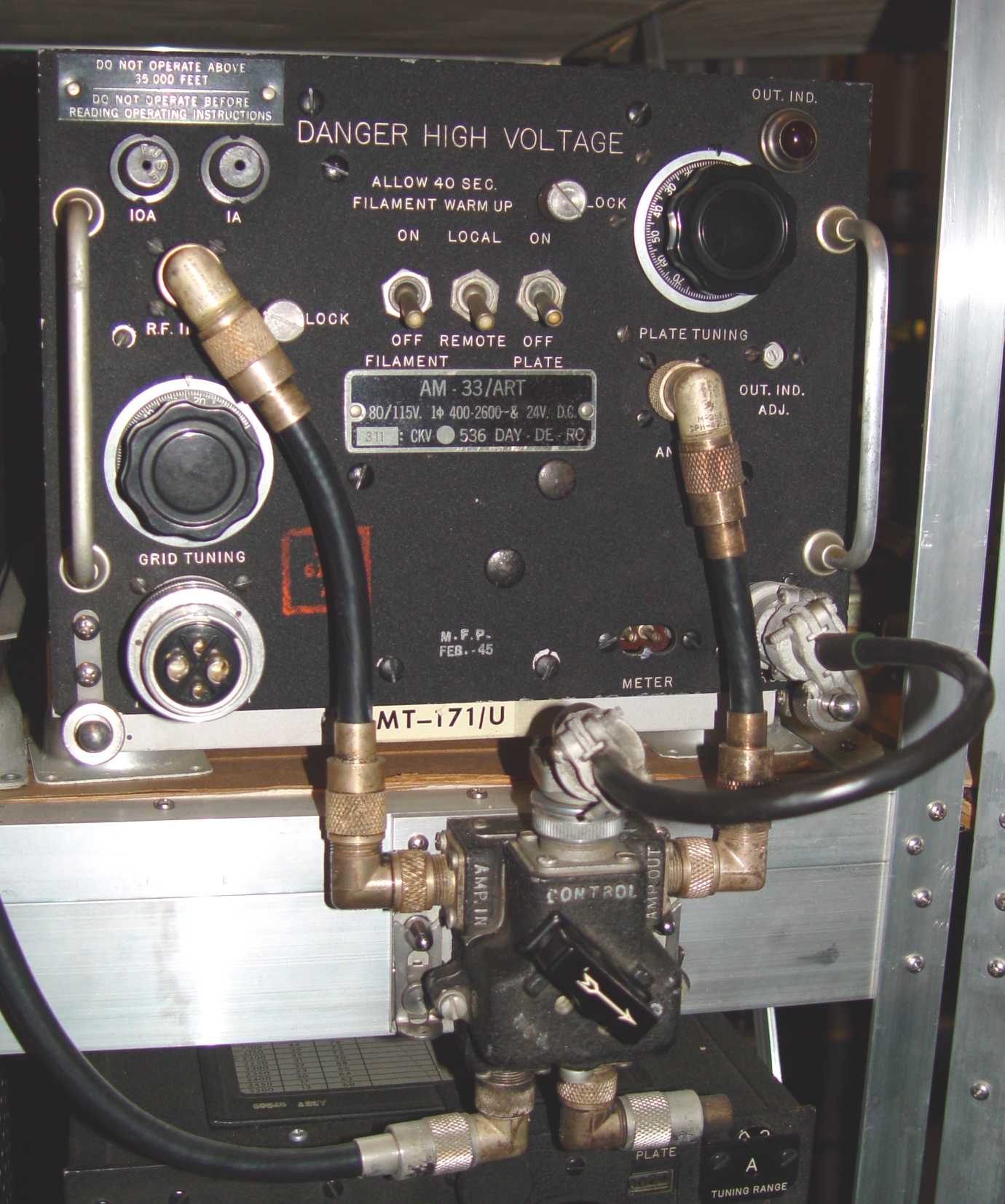
The AM-33 was essentially identical to the AM-14 linear amplifier, but had several spare plug-in tuning coils that permitted covering the band of ~30-100MHz.
Of course, the original operational concept for the ARQ-8 involved tuning around for the German glide bomb control signal, then switching to jamming mode with the receive/transmit switch on the C-93 control box above. The C-198/AR control unit below the AM-33 was introduced to enable the amplifier to be controlled more flexibly, although it would have been better to use a relay from the control box to do both simultaneously. The C-198 (mounting plate was the MT-336/AR) required you to remember to switch the amplifier in after flipping the control box to transmit. The result is somewhat of a kluge, but with 100W out of the amplifier, a single aircraft at high altitude could then cover a much greater part of the battle area.