ART-6 through ART-11 "Jackal" Communications Jammers
This particular unit was one of a series of six jammers targeted against German tank radio traffic.
With one exception (ART-11) they differed only in the frequency range covered by each transmitter.
The frequency dial shows the range of the transmitter, but inexplicably only serves to tune the filter for the "Monitor" output light.
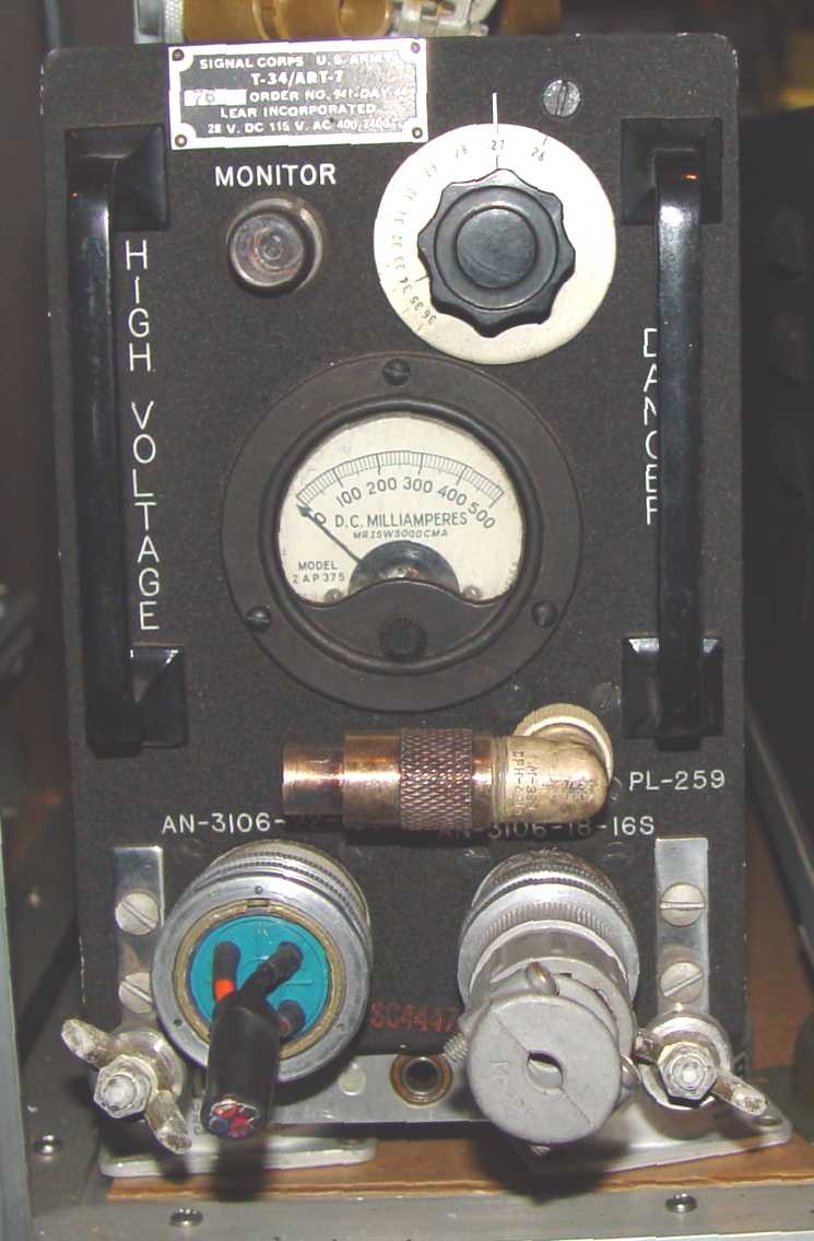
T-34/ART-7 Jammer. Frequency range of this particular jammer was 27 to 34 MHz.
Its basic design was essentially that of a power "flip-flop" oscillator with tuned elements, using a pair of 35TG triodes,
which means that its harmonic content was quite high - so much so that eventually an outboard low pass filter with a cutoff frequency of 76MHz was necessary
to keep its output spectrum from interfering with other aircraft avionics (an F-15/U, made by a small company called
Drake Engineering (with the Acquisition Code CAQW), that would ultimately become a great ham radio company). The frequency was swept back and forth
through its entire frequency range by a ball bearing mounted capacitor driven by the cooling fan motor. The ART-11 differed
from the rest of the series in that it had spare inductors mounted next to the motor, which could be paralleled with
the sweeping capacitor to narrow its jamming band to any 2.5MHz segment within its basic 48-75MHz frequency range.
The other jammers all swept their entire bandwidth of 6 to 8MHz, depending on the transmitter.
The power output of this series was fairly high for jammers - 150 watts.
Frequency coverage for the five transmitters was as follows:
ART-6 - 20-28MHz
ART-7 - 27-34MHz
ART-8 - 32-38MHz
ART-9 - 37-43MHz
ART-10 - 42-48MHz
ART-11 - 48-75MHz
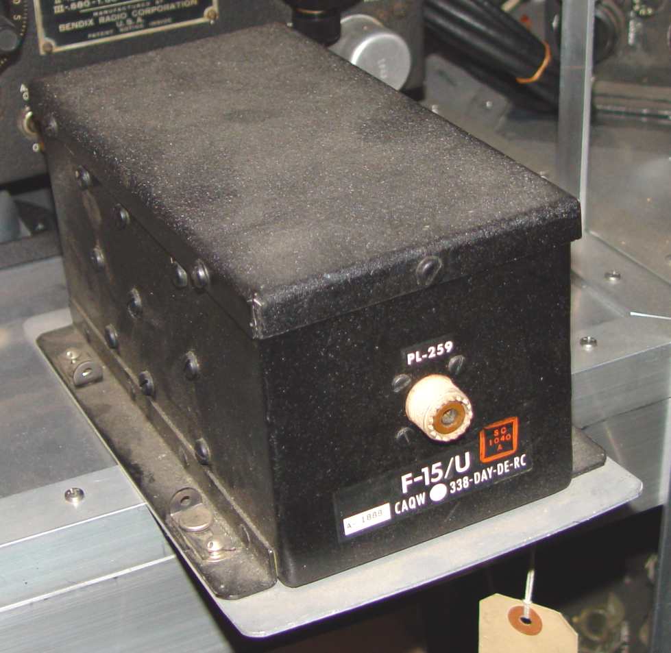
F-15/U harmonic filter. Notice its similarity to later TVI filters used by the ham radio community.
The power supply for all of this series was a similarly sized PP-35/ART, shown below. It used an unusual clock driven power
switch to delay application of B+ until 60 seconds after the filaments were energized. One can hear the timer ticking away
once the power switch is pushed up to "ON".
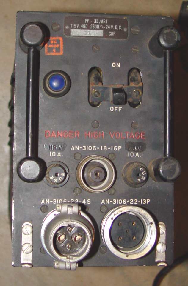
PP-35/ART power supply
The antennas used with this series were a variety of fan (multiple wires radiating from a feed point) and vertical stubs depending on frequency, using a matching
network at the feedpoint of the antenna to minimize VSWR in the feedline coax. It simply goes to show the detailed engineering that went into this system. Nothing
was left to chance with a war on. Shown below are typical of the rare matching networks and antenna bases.
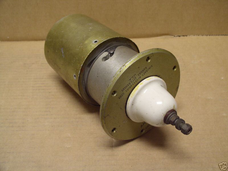
AB-47 and CU-50 for ART-7. This combines the matching network and antenna base into one unit to feed a wire fan antenna.
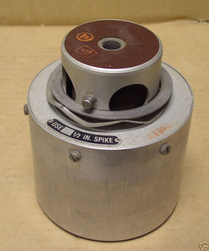
AS-89 matching network for ART-9. This uses the AB-29/ART antenna base below.
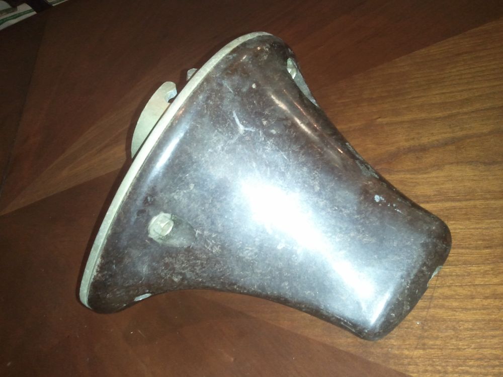
AB-29/ART antenna base. An appropriate length spike threads in from the top at the right end.
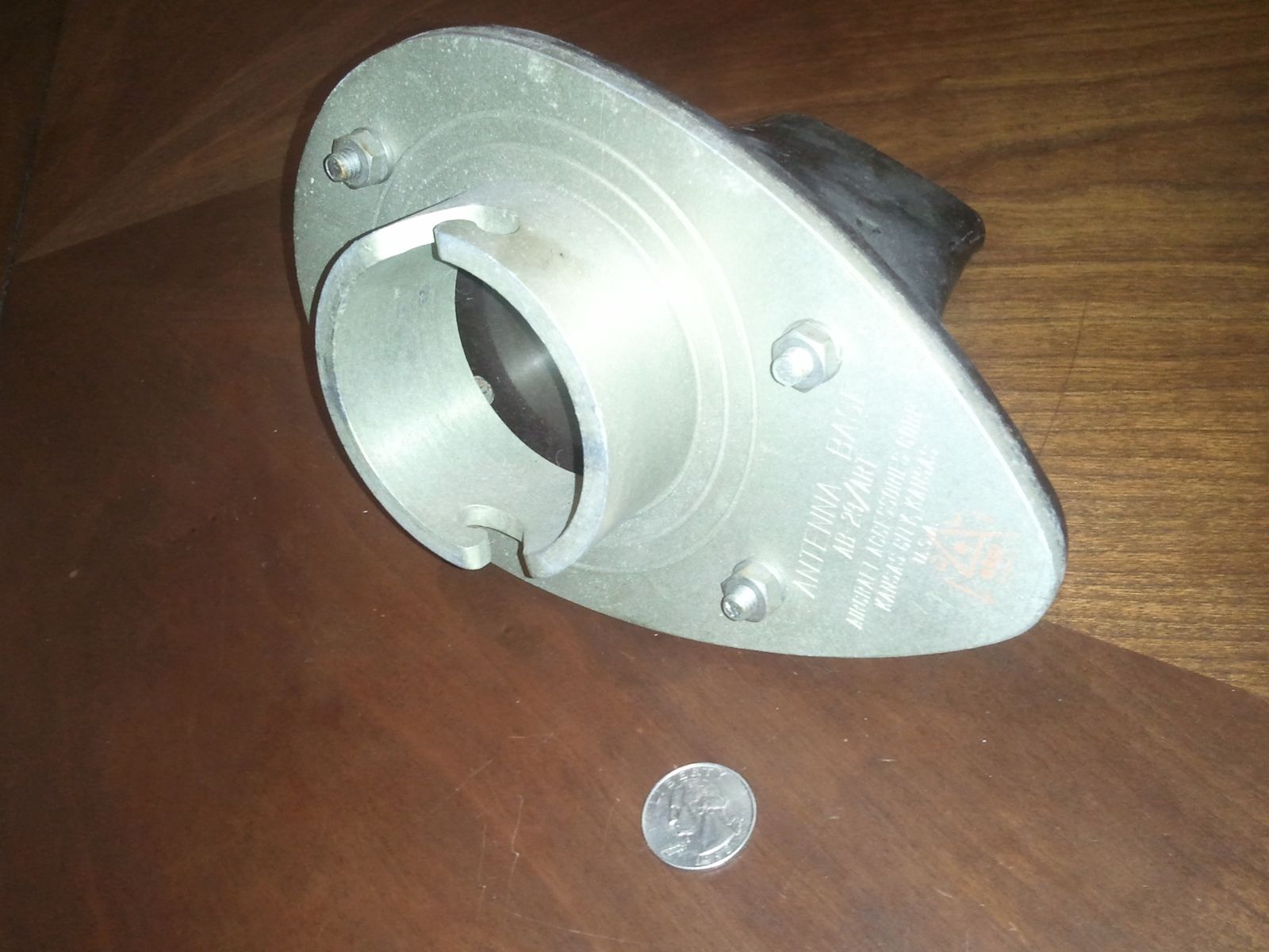
AB-29/ART antenna base bottom view
Return to AAFRadio