Gorgon 2A
Designed for air to air use in 1944, the Gorgon 2A was one of a series of Navy missiles that used a
variety of aiming techniques. This particular model employed one of the original "Block 1" RCA television
cameras with an integral transmitter, thus the clear plexiglass nose. Nothing remains of the camera,
unfortunately.
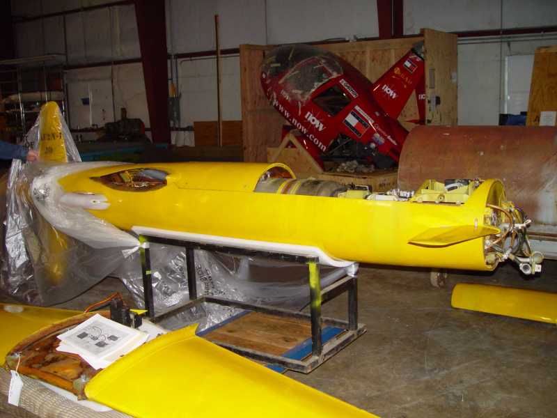 Overall view
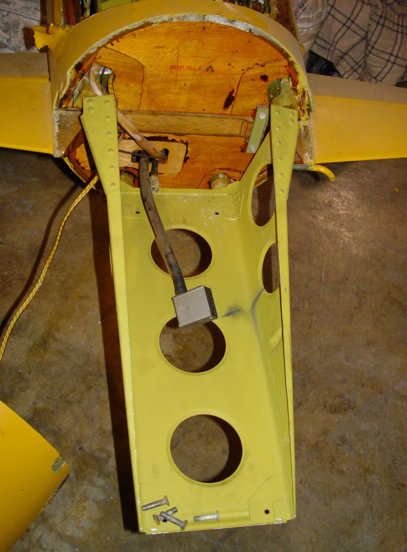
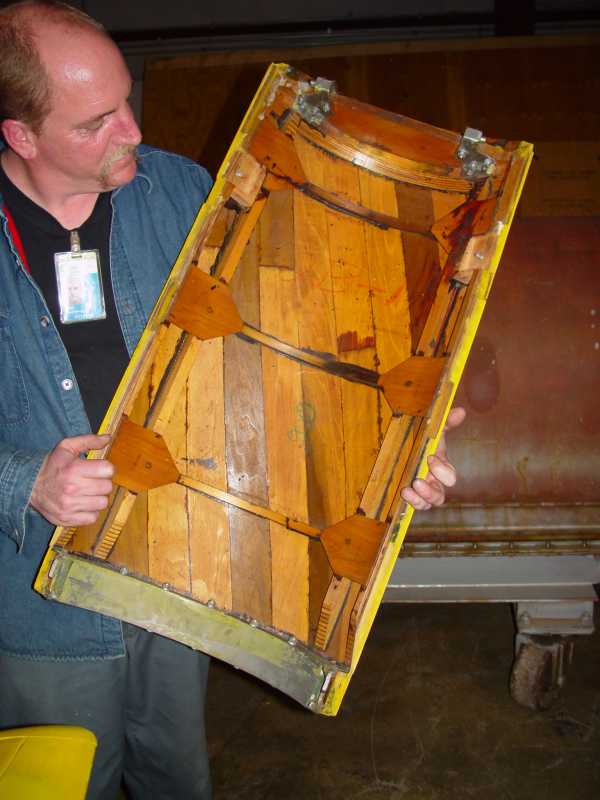 Top cover removed - notice the beautiful wood craftsmanship
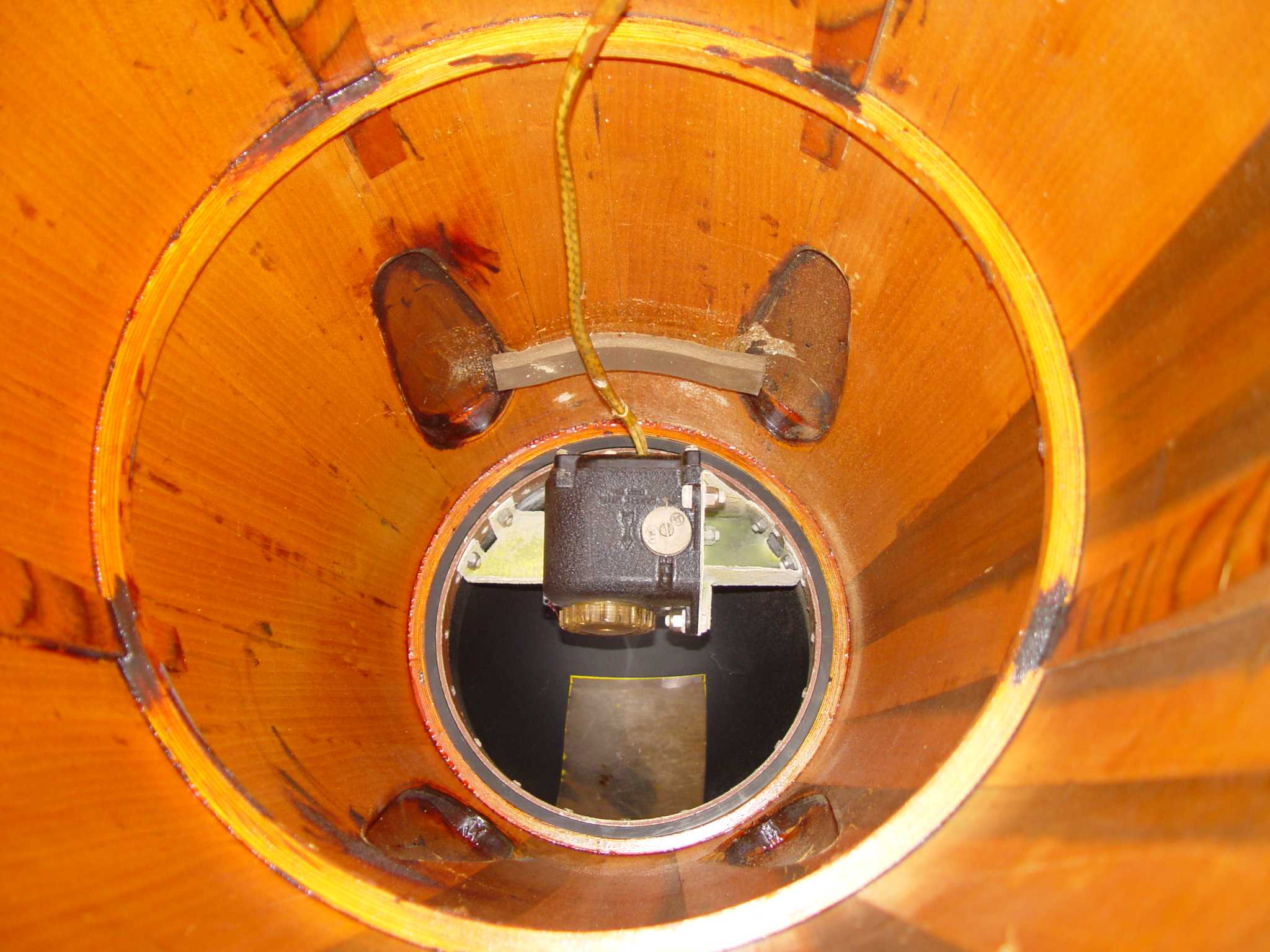
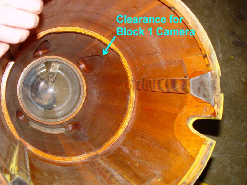 Nose cone
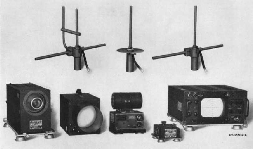
Block 1 TV system. The camera is on the left.
Only the camera and dynamotor pictured above were mounted in the Gorgon 2A. The antenna for the television
transmitter and the one for the control receiver were built into the wing to minimize drag at the high
speeds capable with the liquid propellent motor. With the dimensions of the TV camera and dynamotor (thanks, Maurice!), it was possible to
confirm the Block 1 equipment design, but we lack any documentary details on the RAY-3 control receiver
that documents suggest was installed in the Gorgon 2A. If anyone has a manual they can reference, I would appreciate a note to
aaf-radio-1@aafradio.org. The RAY-3 was redesignated as AN/ARW-22(_)X when the JAN nomenclature systems was
introduced, so the manual may be titled under that number. The
subsequent recovery of the other Gorgon 2A in the collection from its perch high in the rafters didn't help -
the control receiver was there but it has a different nomenclature - PR6N, shown below. This may just be a
manufactur's model number, however.
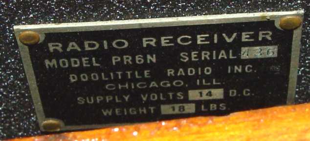 Control Receiver
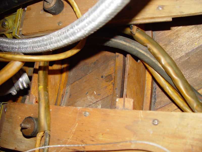
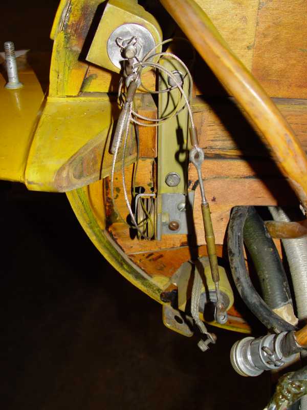 Nose Control Cables. These mirrored the cables going to the wing control surfaces in the first missile.
It is not clear what these cables accomplished. They are not present in the Museum's other example of the
Gorgon 2A.
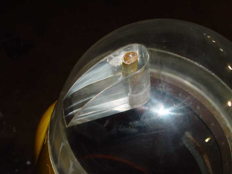 Nose plexiglas
The large reinforcement shown glued to the inner radius of the nose plexiglas is still an unknown at this
point. Given the control cables from the flight controllers leading into the nose cone, it initially seemed
possible that the camera might have been mounted on a gimbal at the front, allowing the missile to follow where
the camera was pointing. Such a design might have assisted in solving the almost impossible problem of maintaining
visual lock on the target in the final few seconds of flight, especially in an air-to-air situation. That would
have required a stout mount for the front of the gimbal. However, there was
almost no room for a camera the size of a Block 1 version to do any swiveling. Unveiling the second missile
did not help - there was no such mount in its nose and the camera mount was fixed. On the other hand, it did
illustrate the developmental nature of the series.
The second artifact was discovered to have all the components in it except the camera, and bore some
interesting differences in configuration from the one now hanging in the Udvar-Hazy Museum. In this second
missile, no control cables were located in the nose cone at all, and the "impact fuse" was one commonly
used in WWII as a "crash switch" to destroy classified IFF equipment in the event an aircraft was shot
down.
 Second artifact nose cone. Note the SA-3A / BC-706 "crash switch" used as an impact detector.
 Second artifact camera mount. The connector identifies it as a Block 1 camera.
No room was available for the planned 200lb. warhead in any of these examples. A parachute was installed on top
of the control receiver and dynamotor in the second missle to permit recovery after each live fire test.
 RAY-3 (ARW-22(_)X) Control receiver mount. Shown here are the front two shocks.
 Dynamotor mount
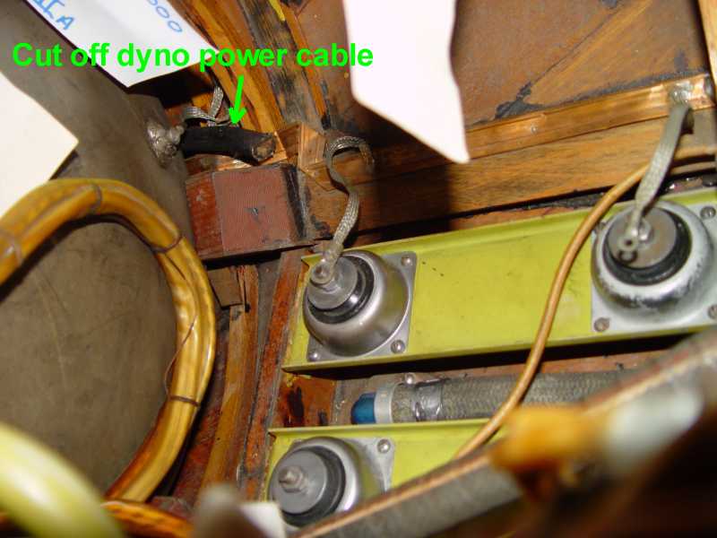
The discovery of the complete interior in the second Gorgon was a welcome suprise, but it brought its own
puzzles. In addition to the control receiver in the correct location, the battery tray in the first missile
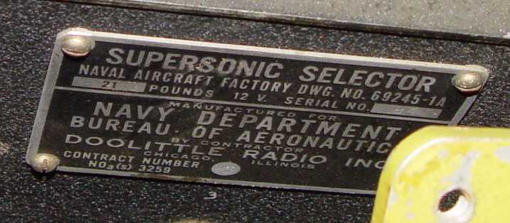
was missing in the second, replaced by another component about the same size, entitled "Supersonic
Selector". This is cabled to the control receiver, but shares a connection to the antenna.
 Second telemetry box. Purpose of this is as yet unclear.